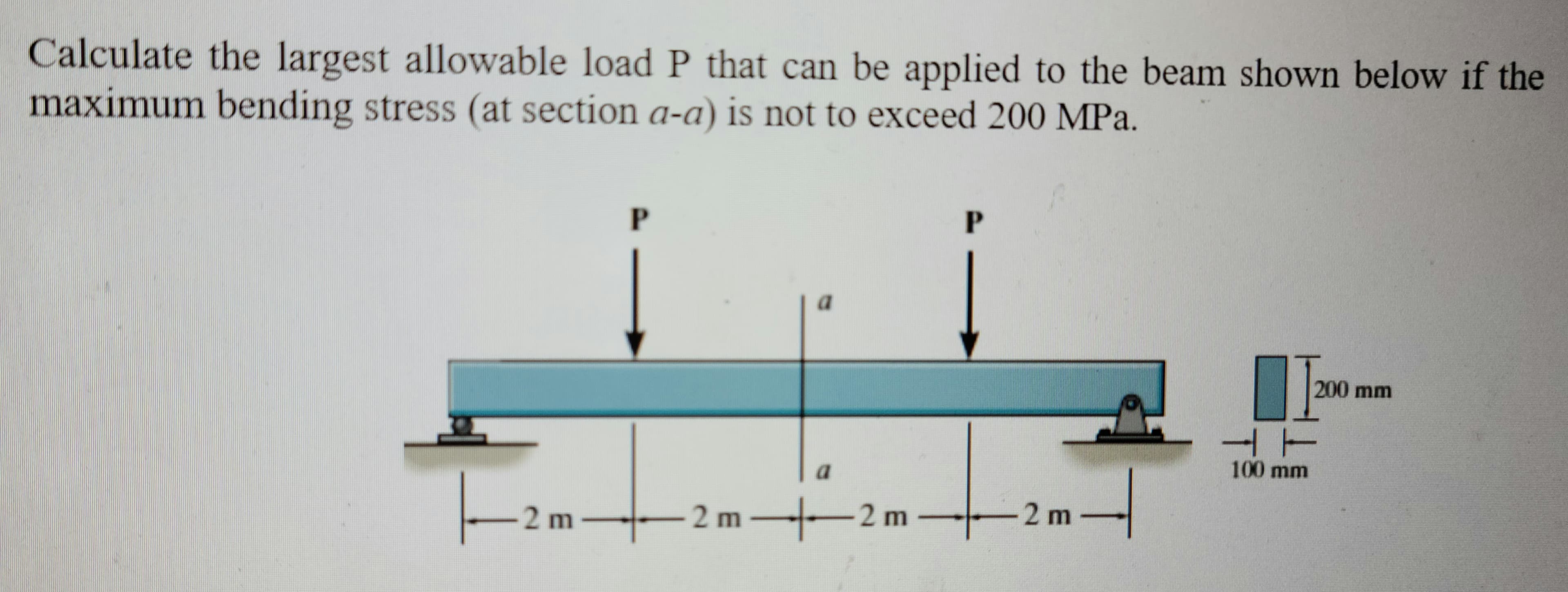
Calculate the largest allowable load P that can be applied to the beam shown below if the maximum bending stress (at section a-a) is not to exceed 200 MPa.
Q: Figure Q6 shows the cantilevered 6061-T6 aluminum alloy rectangular beam fixed at A. Given Modulus…
A:
Q: Determine the maximum normal stress (MPa) due to bending for the beam and loading condition shown in…
A: Given Data: The section modulus of the beam is, S=475225 mm3=475225 mm3×m1000 mm3=4.752×10⁻⁴ m4.
Q: For the beam loaded as shown in figure determine the maximum moment.
A:
Q: A beam 8 m span is freely supported at its ends and a udl of 40 KN/m is spread over the whole span…
A: The schematic diagram of the beam is as follows: The free body diagram of the beam is as follows:
Q: A cantilever beam L meters long carries a uniformly distributed load of 6.8 KN/m over its entire…
A: Given, w = 6.8 kN/m fb = 110 MPa
Q: The simple beam AB, shown below, supports a concentrated load of 22 kN and a segment of a…
A:
Q: Calculate the shear stress of the beam in the figure at point “a”?
A: Moment of inertia of an area is defined as the product of area and the distances of its center from…
Q: Calculate the maximum shear stress T and the max maximum bending stress o in a simply supported wood…
A:
Q: The simply supported beam of circular cross section carries a uniformly distributed load of…
A:
Q: Determine the largest allowable value of P if the bending stress for simply supported beam (shown in…
A:
Q: A beam with the cross-section shown is carrying a bending moment of M. Calculate the maximum bending…
A:
Q: Answer as soon as possible
A: Given data as per the question Uniform distributed load value = 2.5 k/ft data is taken as from the…
Q: If w = 25 kN/m., calculate the value of EIδ at 1 m. of the free end of the loaded beam as indicated…
A:
Q: A floor system in a small building consistsof wood planks supported by 2-in. (nominal width)joists…
A: Given Length, L = 10.5 ft = 126 in. w = floor load = 120 lb/ft2 = 0.8333…
Q: Calculate the maximum bending stress for beam shown below, if P = 47 kN, d = 80 mm and b = 200 mm.
A:
Q: Class A cantilever beam AB of circular cross section and length L=450 mm supports a load P-400 N…
A:
Q: Compute the maximum bending moment, maxi- mum deflection and the maximum bending stress for a…
A: For a railroad rail subjected to a single wheel load of 100 kN, we must calculate the maximum…
Q: Problem 3: Calculate the maximum shear stress in the following beam section due to an internal shear…
A: Find the maximum shear stress .
Q: 6.21-6.38 For the beam shown, derive the expressions for V and M, and draw the shear force and…
A:
Q: .A steel simply supported beam 16 ft and 8 inches in length is subjected to a concentrated load of…
A:
Q: Write shear and bending moment equation and draw it for beam loading as shown in Fig. below: 4 kN m…
A: As per the guidelines of BARTLEBY we are subjected to solve only one question at a time. Please…
Q: A 5-m simply supported beam with an additional 2-m overhang carries a point load equal to 45 kN at…
A:
Q: An I-section shown in Fig. is simply supported over a span of 15 m. If the maximum permissible…
A:
Q: A thin strip of hard copper (E = 16,000 ksi) having length L= 90 in, and thickness t=3/32 in. is…
A: Given data:- Modulus of elasticity, E=16000ksi=110.316GPa Length of strip, l=90in=2.286m thickness,…
Q: of the beam are breadth, b = 35 mm and depth d = 125 mm. Calculate the maximum bending stress and…
A:
Q: Draw the shear-bending moment diagram of the beam shown. Calculate the maximum normal stress due to…
A: To find: The shear and bending diagram The maximum normal stress due to bending
Q: For the next Beam in Cantiléver; Calculate the Maximum Compressive and Tensile Stresses Due to…
A:
Q: Calculate the vertical collapse of the B end of a rectangular beam with one end supported by a fixed…
A:
Q: Maximum bending stress increases with the decrease in height for a rectangular cross-section beam.…
A: GIVEN DATA STATEMENT GIVEN - Maximum bending stress increases with the decrease in height for a…
Q: A wooden beam of cross-section 80 mm × 240 mm rests on an earth foundation. The modulus of…
A: A wooden beam with a cross section of 80 mm×240 mm is known to sit on an earth base.Wood has a…
Q: A rectangular beam experienced a bending moment of 100 kN-m. The width of the beam is 2 m and…
A: Given:M=100 KN.mb=2 mσb=10 MPa
Q: A overhang beam hanged at B(6m) has two loads of 8 & 4 kn at 6 and 9 m. Calulate its moment using…
A:
Q: A simply supported wood beam having a span length L=12ft is subjected to unsymmetrical point loads.…
A:
Q: The figure below demonstrates a beam simply supported, subjected to a load fixed1177 kn Considering…
A:
Q: For the beam shown below, draw bending stress distribution along the depth of beam at mid span…
A: To find the Bending stress distribution in the given beam:
Q: As shown in the figure below, determine the internal loadings at points D and. Consider the weight…
A:
Q: Draw a complete shearing force and a bending moment diagram for the for the beam shown in the…
A:
Q: . The wide-flange I beam as shown is 20 ft. long. It is fixed at one end and free at the other. A…
A: Given that, I=30,000 lb·in,E=30×106 psi,G=12×106 psi,T=30,000 lb·in,L=20 ft, The given I-section…
Q: Cantilever beam loaded as shown in fig., draw the shear force diagram and bending moment diagram. 20…
A:
Q: A Portable Crane will be designed as shown in Figure which is able to withstand dynamic loads. Th…
A:
Q: For the beam below, calculate: 1) the support reactions; 2) develop the shear and bending moment…
A:
Q: A beam of I section 200 mm wide and 300mm deep with flange and web thickness 20 mm is used as a…
A:
solve
Trending now
This is a popular solution!
Step by step
Solved in 3 steps with 3 images
- A weight W = 4000 lb falls through a height h = 0.5 in, onto the midpoint of a simple beam of length L = 10 ft (see figure). Assuming that the allowable bending stress in the beam is = 18,000 psi and E = 30 x 10* psi, select the lightest wide-flange beam listed in Table F-l(a) in Appendix F that will be satisfactory.A rectangular beam with semicircular notches, as shown in part b of the figure, has dimensions h = 0,88 in. and h1 = 0.80 in. The maximum allowable bending stress in the metal beam is emax = 60 ksi, and the bending moment is M = 600 lb-in. Determine the minimum permissible width bminof the beam.A weight W = 20 kN falls through a height h = 1,0 mm onto the midpoint or a simple beam of length L = 3 m (see figure). The beam is made of wood with square cross section (dimension don each side) and E = 12 GPa. If the allowable bending stress in the wood is °aLLow =10MPa, what is the minimum required dimension
- A floor system in a small building consists of wood planks supported by 2-in. (nominal width) joists spaced at distance s and measured from center to center (see figure). The span length L of each joist is 12 ft, the spacing s of the joists is 16 in., and the allowable bending stress in the wood is 1250 psi. The uniform floor load is 120 lb/ft", which includes an allowance for the weight of the floor system itself. Calculate the required section modulus S for the joists, and then select a suitable joist size (surfaced lumber) from Appendix G, assuming that each joist may be represented as a simple beam carrying a uniform load. What is the maximum floor load that can be applied to your final beam selection in part (a)?A square tube section has side dimension of 20 in. arid thickness of 0.5 in. If the section is used for a 10-ft-long beam subjected to 1250 kip-in, torque at both ends, calculate the maximum shear stress and the angle of twist between the ends. Use G = 11,600 ksi.A simply supported beam is loaded with a point load, as shown in the figure. The beam is a steel wide flange shape (W 12 ×35) in strong axis bending. Calculate the maximum deflection of the beam and the rotation at joint A if L = 10 ft, a = 7 ft, b = 3 ft, and P = 10 kips. Neglect the weight of the beam.
- A frame ABCD is constructed of steel wide-flange members (W8 x 21; E = 30 x ID6 psi) and subjected to triangularly distributed loads of maximum intensity q0acting along the vertical members (see figure). The distance between supports is L = 20 ft and the height of the frame is h = 4 ft. The members are rigidly connected at B and C. Calculate the intensity of load q0 required to produce a maximum bending moment of 80 kip-in. in the horizontal member BC. If the load q0 is reduced to one-half of the value calculated in part (a), what is the maximum bending moment in member BC? What is the ratio of this moment to the moment of 80 kip-in. in part (a)?Solve the preceding problem for a wide-flange beam with h = 404 mm, b = 140 mm, bf= 11.2 mm, and rf. = 6.99 mm.The wood joists supporting a plank Floor (see figure) are 38 mm × 220 mm in cross section (actual dimensions) and have a span length of L = 4.0 m. The floor load is 5.0 kPa, which includes the weight of the joists and the floor. (a) Calculate the maximum permissible spacing s of the joists if the allowable bending stress is 14 M Pa. (Assume that each joist may be represented as a simple beam carrying a uniform load.) (b) If spacing s = 406 mm, what is the required depth ft of the joist? Assume all other variables remain unchanged.
- A rectangular beam with semicircular notches, as shown in part b of the figure, has dimensions h = 120 mm and h1= 100 mm. The maximum allowable bending stress in the plastic beam is emix = 6 M Pa, and the bending moment is M = 150 N · m. Determine the minimum permissible width bminof the beam.-15 A composite beam is constructed froma wood beam (3 in. x 6 in.) and a steel plate (3 in, wide). The wood and the steel are securely fastened to act as a single beam. The beam is subjected to a positive bending moment M. = 75 kip-in. Calculate the required thickness of the steel plate based on the following limit states: Allowable compressive stress in the wood = 2 ksi Allowable tensile stress in the wood = 2 ksi Allowable tensile stress in the steel plate = 16 ksi Assume that Ew= 1,500 ksi and es= 30,000 ksi.The cross section of a rectangular beam having a width b and height h is shown in part a of the figure. For reasons unknown to the beam designer, it is planned to add structural projections of width b/9 and height d/9 the top and bottom of the beam (see part b of the figure). For what values of d is the bending-moment capacity of the beam increased? For what values is it decreased?