Calculate the passive earth pressure coefficient for the foundation soil to the right of the toe of the wall using the Rankine Earth Pressure theory. On Figure 1, sketch the passive pressure distribution and calculate the resultant force(s). Show the resultant, and its location, on your sketch. AND Sketch the wall and the distribution of lateral earth pressures resulting from the backfill for the Coulomb case, assuming good drainage. Call this “Figure 2: Coulomb Active Earth Pressures from Backfill.” Calculate the resultant horizontal and vertical forces and add them to your sketch. Indicate clearly the location of the resultant forces.
Calculate the passive earth pressure coefficient for the foundation soil to the right of the toe of the wall using the Rankine Earth Pressure theory. On Figure 1, sketch the passive pressure distribution and calculate the resultant force(s). Show the resultant, and its location, on your sketch. AND Sketch the wall and the distribution of lateral earth pressures resulting from the backfill for the Coulomb case, assuming good drainage. Call this “Figure 2: Coulomb Active Earth Pressures from Backfill.” Calculate the resultant horizontal and vertical forces and add them to your sketch. Indicate clearly the location of the resultant forces.

Principles of Geotechnical Engineering (MindTap Course List)
9th Edition
ISBN:9781305970939
Author:Braja M. Das, Khaled Sobhan
Publisher:Braja M. Das, Khaled Sobhan
Chapter15: Slope Stability
Section: Chapter Questions
Problem 15.14P

Related questions
Question
100%
Calculate the passive earth pressure coefficient for the foundation soil to the right of the
toe of the wall using the Rankine Earth Pressure theory. On Figure 1, sketch the passive
pressure distribution and calculate the resultant force(s). Show the resultant, and its
location, on your sketch.
AND Sketch the wall and the distribution of lateral earth pressures resulting from the backfill
for the Coulomb case, assuming good drainage. Call this “Figure 2: Coulomb Active Earth
Pressures from Backfill.” Calculate the resultant horizontal and vertical forces and add
them to your sketch. Indicate clearly the location of the resultant forces.
Transcribed Image Text:Earth Pressures Analysis
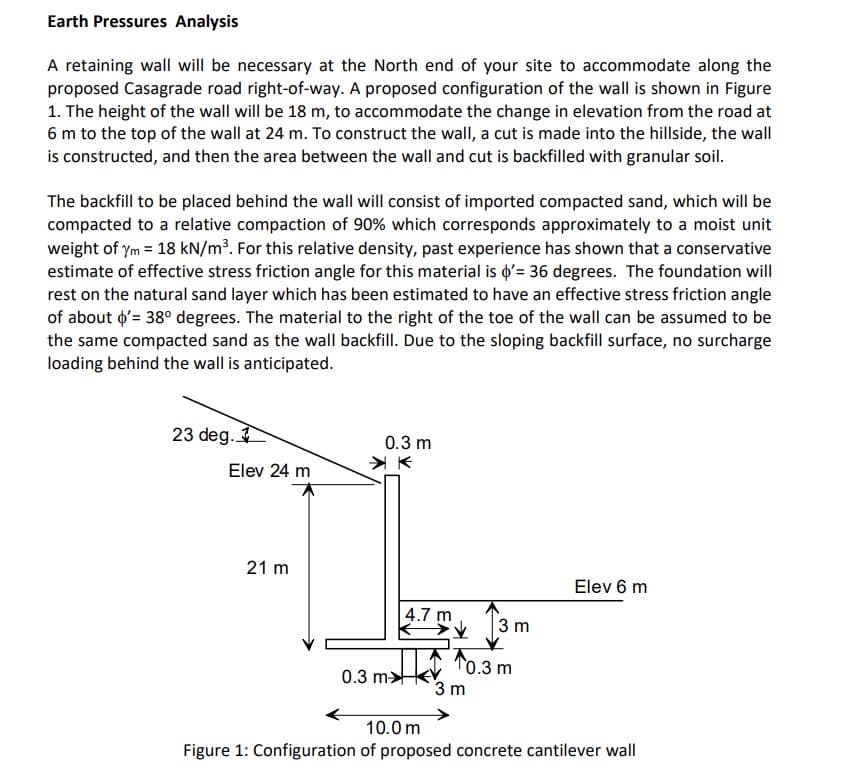
A retaining wall will be necessary at the North end of your site to accommodate along the
proposed Casagrade road right-of-way. A proposed configuration of the wall is shown in Figure
1. The height of the wall will be 18 m, to accommodate the change in elevation from the road at
6 m to the top of the wall at 24 m. To construct the wall, a cut is made into the hillside, the wall
is constructed, and then the area between the wall and cut is backfilled with granular soil.
The backfill to be placed behind the wall will consist of imported compacted sand, which will be
compacted to a relative compaction of 90% which corresponds approximately to a moist unit
weight of ym = 18 kN/m³. For this relative density, past experience has shown that a conservative
estimate of effective stress friction angle for this material is d'= 36 degrees. The foundation will
rest on the natural sand layer which has been estimated to have an effective stress friction angle
of about o'= 38° degrees. The material to the right of the toe of the wall can be assumed to be
the same compacted sand as the wall backfill. Due to the sloping backfill surface, no surcharge
loading behind the wall is anticipated.
23 deg.
0.3 m
Elev 24 m
21 m
Elev 6 m
4.7 m
13m
T0.3 m
3 m
0.3 m>
10.0 m
Figure 1: Configuration of proposed concrete cantilever wall
Expert Solution
This question has been solved!
Explore an expertly crafted, step-by-step solution for a thorough understanding of key concepts.

This is a popular solution!

Trending now
This is a popular solution!

Step by step
Solved in 2 steps with 4 images

Knowledge Booster


Learn more about
Need a deep-dive on the concept behind this application? Look no further. Learn more about this topic, civil-engineering and related others by exploring similar questions and additional content below.Recommended textbooks for you
Principles of Geotechnical Engineering (MindTap C…
Civil Engineering
ISBN:
9781305970939
Author:
Braja M. Das, Khaled Sobhan
Publisher:
Cengage Learning
Principles of Geotechnical Engineering (MindTap C…
Civil Engineering
ISBN:
9781305970939
Author:
Braja M. Das, Khaled Sobhan
Publisher:
Cengage Learning