circuits please help
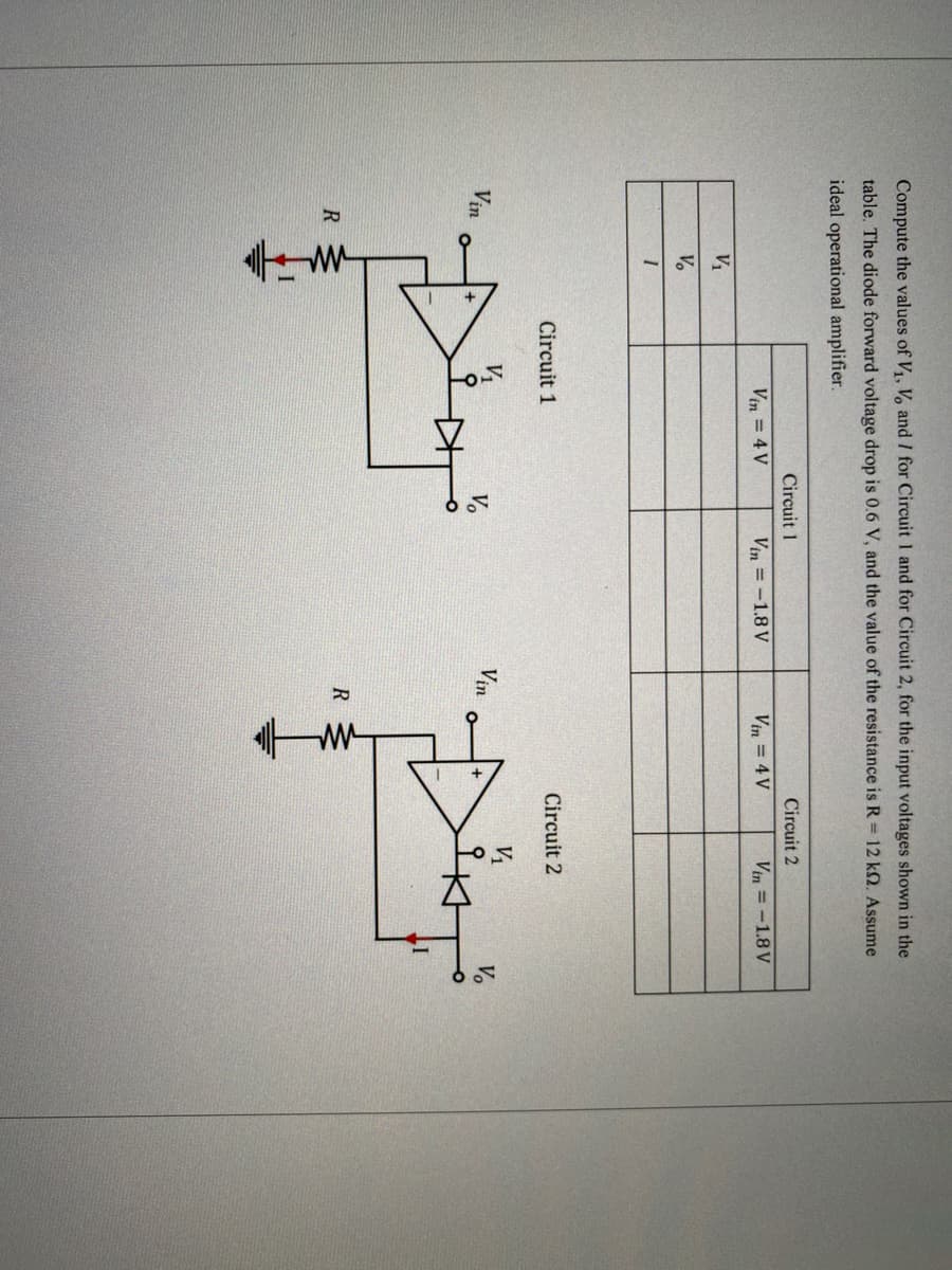
Q: With the circuit below, solve for Va using superposition.
A: The algebraic sum of response of individual sources acting alone is equal to all the sources acting ...
Q: A parallel-plate capacitor has plates of dimensions 2 cm by 3 cm. The plates are separated by 1 mm t...
A:
Q: It is desired to minimize the reflection at the air-dielectric (€, = 15, µ, = 1, o = 0) interface by...
A:
Q: Calculate the locked-motor current for 2 hp, 220 V motor with an J code of 7.1-8.0 KVA/ hp
A:
Q: Given the following delta-connected resistances: Rab = 10 Ω, Rbc = 9 Ω, and Rca = 4 Ω, calculate the...
A:
Q: Voltage input Vin R = 10kN sin(2n X 8t) C = 10µF
A: The given circuit is an RC circuit, with a sinusoidal supply. So, here two types of response exist ...
Q: 15 A the other draws 40 A andthe third 52 A What size ofthe conductor in terms of ampacity may be us...
A: The capacity of feeder circuit = vector sum of all the current drawn by motor because for the motor ...
Q: Find the power dissipated by R2. 30 mA R, = 1 ka www 50 mA R = 2 kn R3 = 2 k. R = 4 k2 www www www
A:
Q: 10 mF 20 Ω 40. Consider the network depicted in Fig. 10.54, and determine the equivalent impedance s...
A: As per our guidelines we are supposed to answer only first question. Kindly repost the other questio...
Q: AM signal from a PAM signal
A: If an input signal's height varies with the loudness of a user's voice and then adds this to the car...
Q: 4. Write simultaneous Laplace-transformed nodal equations for the electrical networks of Figure P1.4...
A:
Q: 5. If the change in the input voltage of a power supply is around 2V and the change in the output vo...
A: Line regulation: Line regulation is defined as the percentage change of output voltage by changing t...
Q: in a triode, what should be done to increase the plate current? Note only vary the Vgg
A: Given, Triode and it's plate current. Note :- only vary the Vgg i.e.., Grid voltage. Please find the...
Q: Draw the quantization level and the error as a function of input signal x, if m3D3 for unipolar and ...
A: Given, m=3 In the quantization process, the different value given to the lower part of the analog s...
Q: 6. Find the frequency spectrum of periodic rectangular pulses in complex exponential form and draw o...
A:
Q: What voltage is boosted at the output of a multiplier. a) average b) rms c) peak d) instantaneou...
A: As per guidelines given to us, we can only provide the solution of one question in multiple type of ...
Q: 25kn 25kn Wr 25kn 25kn 20kn 4kO 10kO 6kQ 25V (* + 3kQ + 1. Compute for the equivalent resistance (in...
A:
Q: When the charge on the capacitor in an ??LC circuit is one‑third of the maximum stored charge, calc...
A:
Q: 2. A Germanium sample is 10 mm long and has a rectangular cross-section, 60 µm by 180 um. A Boron at...
A:
Q: Name the logic circuit AD inputs output Find the expression of F and simplify
A:
Q: For the cascaded binary symmetric channels shown below, find the maximum amount of information trans...
A: Pyx=0.90.10.20.8x2x1Pzy=0.70.30.25450.7455y2y1 Now calculating P(z/x) as Pzx=Pyx.Pzy =0.90....
Q: The diode (blue line) should be at -10V not -8V
A: The Diode-based circuit can be designed in LTspice by selecting the general diode and changing the m...
Q: Let the periodic signal f(t) be shown in the figure, f(t)=f(tT): -T/2 T/4 T/4 T/2 A = 10; T = 2n Fin...
A:
Q: Q4/ A 500 h.p., 3-phase , 440 V, 50 Hz induction motor has a speed of 950 r.p.m. on full-load. The m...
A:
Q: Obtain the truth table of the following functions, and express each function in minterms and/or max...
A:
Q: iven a conventional single-phase transformer is converted to a step-up autotransformer as shown in F...
A: Solution- a) Since 3 phase, 200 KVA so single phase or apparent power of each windings, ...
Q: . When using superposition, what is the ideal internal resistance of a voltage source? The Thevenin ...
A: De activated sources can be replaced by their internal resistances in super position theorem.
Q: the current of 5 A flows through a long wire of diameter of 0.006, what is the magnetic field intens...
A: We need to find magnetic field at given point due to current carrying wire
Q: A 4-pole, 50 hz, 3-phase induction motor has a slip-ring rotor with resistance and standstill reacta...
A: Given,f=50HzR2=0.04 ohm/phaseX2=0.2 ohm/phasesfl=0.03TstTmax=2.smTsmT2+1 ......1TfLTmax=smT.sfLsmT2+...
Q: Ge Si 1.2 kN -10 Vo Voz 3.3 k2
A:
Q: 5) A balanced Y-Y four-wire system has phase voltages Van = 120 20°, Vbn = 1202-120 , Ven = 120 Z120...
A:
Q: Node 1 Reference node Node 1 Node 2 23 sin t Node + v() - Node w cos r(+)Node 6 cos 7e Node 3 Refere...
A:
Q: Engineering students are learning to use phasor diagrams to analyze RLC series circuits. They are gi...
A:
Q: 5/2 2 Vs(t) 0.1 F 10/3 H ele
A:
Q: Q 3. For the circuit shown in Fig. 1, calculate the current through all the branches of the circuit ...
A: Given
Q: 1. In the network shown, the switch is opened at t = 0. Find i(t) at t > 0. t = 0 100 ohms 100 ohms ...
A: as per our guidelines we are supposed to answer?️ only one question. Kindly repost other questions a...
Q: 1. A Silicon diode is operating at a room temperature of 25 °C and has a reverse current of 10 nA. S...
A:
Q: em 5 From the circuit as shown, find V, let R1 =1n R2=7N and R3 =4 R3 ww 42 V-10020 V V, 62 ww
A:
Q: 1- 0.9z-1 - 0.1z? 1 + 0.3z-1 - 0.04z2 H(z) =
A: The solution is given below
Q: 3.4 Determine vỵ in the circuit of Fig. 3.11. using nodel an 2 A 2Ω 8Ω + 30 V 10 Ω U (1)
A: Given circuit shown
Q: Find the transfer function of the following circuit:
A:
Q: A 4-pole , 50hz , 7.46 kW induction motor has at rated voltage and frequency, a starting torque of 1...
A:
Q: ode Rectifier Configurations 3.5.4 Questions & Answers a) In a half-wave rectifier, a diode will pas...
A:
Q: 3. Determine the inverse Laplace transform; s2+1 F(s) = (s+1)²(s²+4)
A:
Q: 2. For the voltage regulator shown in Figure below, VO =9 Vand R1=1k0. Calculate the value of R2. In...
A: The solution is given below
Q: L1 R1 C1 V1 V2 R2.
A:
Q: 1. A moving-coil instrument gives f.s.d. for a cur- rent of 10 mA. Neglecting the resistance of the ...
A:
Q: L1 el 9.7µ 7.8m V1 C2 R1 5.4µ 5.1k AC 0.4 0 R2 =>f = 20 kHz 760
A:
Q: TRY SOLVING THIS! Twenty seven spherical drops, each of radius 3 mm and carrying 0.5 pC of charge ar...
A:
Q: 4. A moving-coil instrument has a f.s.d. of 20 mA and a resistance of 25 2. Calculate the values of ...
A:
Step by step
Solved in 3 steps with 3 images
- A loaded zener regulator has a VZ of 11 V with IZ equal to 23 mA, with IZK equal to 0.25 mA, ZZ equal to 8 Ω and a PD (max) equal to 1 W. The value of the resistance R is equal to 32 Ω. Determine the values of the output voltage with IZK and IZM. Get the value of the minimum load resistance that can be used to keep the zener diode regulating.Zener voltage, VZ = 6.1V and incremental resistance, rz = 0 a) Determine the value of Ri such that the Zener diode remains in breakdown if the load current varies from IL = 20 to 200 mA and if the input voltage varies from VI = 8.6 to 10V. Assume IZ(min) = 0.1IZ(max). b) Determine the power rating required for the Zener diode and the load resistor. c) If the position of Zener diode were changed to be in forward bias region, will the voltage regulator still work properly? Justify your answerCalculate the power rating of a zener diode connected across load working in reverse biased condition when the breakdown occurs at the current twice the test current, where VZ = 30 V, VZK =28.5V, IZK= 2mA, IZ= 10mA . Also calculate the minimum load resistance value with input voltage at Vs= 60 V and series resistance 450ohms.
- Calculate diode forward current IF, diode voltage VF, and voltage drop across series resistor for three diode models (ideal, practical and complex). Assume diode forward resistance (dynamic resistance) r’d = 25Ω. Reverse leakage current IR = 75A with series resistance of RL = 100kΩ in reverse bias. Draw equivalent circuit diagrams of each model separately and plot corresponding I/V characteristics for each model.Calculate diode forward current IF, diode voltage VF, and voltage drop across series resistor for three diode models (ideal, practical and complex).Assume diode forward resistance (dynamic resistance) r’d = 25Ω. Reverse leakage current IR = 75 nanoA with series resistance of RL = 100kΩ in reverse bias. Draw equivalent circuit diagrams of each model separately and plot corresponding I/V characteristics for each model.For the values of R1=230, R2=230, R3=400, Vs=15. If the real diode (offset voltage=0.7V) were conduxting, then the value of voltage source Vb should be? solve correct or will dislike
- 2b) A regulator curcuit needs to be designed with an input power supply which has a nominal value of V_PS=20 V and can vary by ± %25 and nominal output voltage of 10 volts. For this purpose a zener diode is employed with specifications given; power rating of 1 W, 10V drop at Iz=25 mA, output load current is to vary between I(subscript L)=0-20 mA and zener resistance of r_Z=5Ω i) If the minimum Zener current is to be I_Z=5 mA, determine the required R_S ii) Determine the maximum variation in output voltage iii) Determine the regulation percentA 10 V Zener diode is used to regulate the voltage across a variable loadresistor. The input voltage Vs varies between 13 and16 V. The loadcurrent (??) varies between 10 and 85 mA. The minimum Zener current is15 mA. Findi. The maximum value of Rsii. The maximum power dissipated by the Zener diode, using the value ofRs.b. using the conventional current flow, where is the direction of the current during the positive cycle at node A.c. Where is the direction of the current during positive cycle at node B.d. draw the output waveform(use the idea diode model)