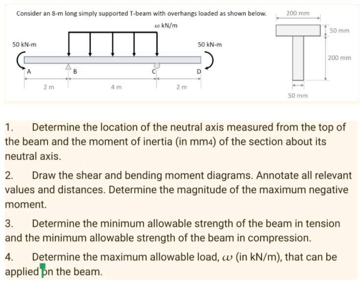
Consider an 8-m long simply supported T-beam with overhangs loaded as shown below. 200 mm w kN/m 50 mm 50 kN-m 50 kN-m 200 mm 2 m 4 m 2 m 50 mm 1. Determine the location of the neutral axis measured from the top of the beam and the moment of inertia (in mm4) of the section about its neutral axis.
Q: A symmetrical Inverted T section has the following specifications : Width of the web (W) = 100…
A:
Q: The cross section of a bearing block is shown in the figure by the shaded area. Calculate the moment…
A:
Q: Given the value of moment of Inertia is 120 x 10^6 mm^4, and the modulus of elasticity of concrete=…
A:
Q: Determine the moment of inertia about the x-axis for the cross-section of the beam shown below.
A:
Q: Face Sheet 3 Face Sheet 2 Total Foam
A: The shape of cross-section of face sheets are rectangular. The area moment inertial of a…
Q: 1) For the given hollow rectangular cross section, find: 8cm a) Moment of inertia according to x…
A: Solution: First, we need to find the location of centroid C of the given rectangular hollow cross,…
Q: For a beam with the cross-section shown, calculate the moment of inertia about the z axis. Assume…
A:
Q: A composite beam is made of two brass [E = 92 GPa] plates bonded to an aluminum [E = 71 GPa] bar, as…
A: For solution refer below images.
Q: A hollow mast of circular section as shown is to be stiffened by bonding two strips of the same…
A: Find the value of h.
Q: The cross section of a bearing block is shown in the figure by the shaded area. Calculate the moment…
A: Answer: Ia-a = 3575.136 in4.
Q: y 2 3 2 2 L=48| 5 6 In the given profile section: a) center of gravity b) the moment of inertia…
A:
Q: The beam in Fig. a is fixed supported to the wall at A and pin connected to a 12-in.-diameter rod…
A: Given data: The diameter of rod, d = 12 in. The modulus of elasticity is, E = 29×103 The moment of…
Q: The cross section of a bearing block is shown in the figure by the shaded area. Calculate the moment…
A: b= 11 in h= 3 in r= 2 in R= 4 in
Q: A beam is constructed by welding two C152 x 16 channels together back to back and welding two C178 x…
A:
Q: Q 3: The steel pipe of outer radius 20 mm and inner radius 18 mm and an aluminum alloy section is of…
A:
Q: The cross section of a bearing block is shown in the figure by the shaded area. Calculate the moment…
A:
Q: Consider the beam's cross-sectional area shown. Suppose that a = 5 in. , b = 8 in. , and c = 1 in.…
A:
Q: The cross section of a bearing block is shown in the figure by the shaded area. Calculate the moment…
A:
Q: The cross section of a bearing block is shown in the figure by the shaded area. Calculate the moment…
A:
Q: A hollow mast of circular section as shown is to be stiffened by bonding two strips of the same…
A:
Q: The dimensions of the double-box beam cross section shown in Figure are (b= 150 mm), (d= 50 mm), and…
A: Write the given data with suitable variables. b=150 mmd=50 mmt=4 mm
Q: For the L5 x 3 x 1/2-in. angle cross section shown, use Mohr’s circle to determine (a) the moments…
A: Dimension of L ,5 in X 3 in X 0.5 in
Q: The cross section of a bearing block is shown in the figure by the shaded area. Calculate the moment…
A:
Q: AT beam is made up of two plates and two angles as shown in the figure. Determine the moment of…
A:
Q: The cross section of a bearing block is shown in the figure by the shaded area. Calculate the moment…
A:
Q: If w = 37 mm, find the moment of inertia about the z axis. The centroid of the section is located…
A:
Q: A hollow mast of circular section as shown is to be stiffened by bonding two strips of the same…
A:
Q: The figure shows cross-section of a beam subjected to bending. The are moment of inertia (in mm4) of…
A:
Q: The cross section of a bearing block is shown in the figure by the shaded area. Calculate the moment…
A:
Q: The cross section of a bearing block is shown in the figure by the shaded area. Calculate the moment…
A: The above diagram consist of three simple figures : 1. Rectangle 2. Circle 3. semi-circle
Q: A beam with a solid homogeneous rectangular section is simply supported at A and B. A concentrated…
A: Given b=35mm d=125 mm
Q: For the circular cross section shown, the value of moment of Inertia (I) is :equal to D=6 in 31 x…
A:
Q: CALCULATE THE MOMENT OF INERTIA OF THE SECTION WITH RESPECT TO THE AXIS OF THE BENDING MOMENT WHICH…
A:
Q: 50 mm 200 mm 50 mm Neutral Axis (N.A) 25 mm Reference Line For the cross section shown, find: 1- The…
A:
Q: The cross section of a bearing block is shown in the figure by the shaded area. Calculate the moment…
A:
Q: The shear stress and the polar moment of inertia are inversely proportional.
A: For solution refer below images.
Q: The moment of Inertia for rectangular cross section is b * h3 h 12 b True False For the rectangular…
A:
Q: Q5/ Blocks of wood together to form the shaded section shown in the figure. Find the moment of…
A:
Q: 50 mm 200 mm 50 mm Neutral Axis (N.A) 25 mm Reference Line For the cross section shown, find: 1- The…
A:
Q: The cross section of a bearing block is shown in the figure by the shaded area. Calculate the moment…
A: Given:b=30 inh=6 inr=4 inR=8 in
Q: olid steel post is subjected to pure torsion. Given: -post Diameter = 65 mm -length = 2.75 m…
A: Given:Diameter, d=65 mm or 0.065 mlength, l=2.75 mtorque, T=2.4 kN-mG=78 GPa
Q: ヘり 1-m O.15-m 0.25-m | 0,15-m² 0. 25-m 1-m 0,75tm --->> 0.15-m
A: In order to find the moment of inertia about x and y axes, we have to convert this cross-section…
Q: For the part below that consists of a semicircle on top of a rectangle, with r = 4 in and h= 9 in,…
A: a. Centroid :
Q: Ex.2: Determine the moment of inertia of the beam cross section about the x axis. 160
A: This question is based on the T-section. So, firstly we find out the centroid of this T-section.…
Q: HW.2 For the shaded area shown in figure below, assume a value for a and find the following: 1-…
A:
Q: The cross section of a bearing block is shown in the figure by the shaded area. Calculate the moment…
A:
Q: HW.2 For the shaded area shown in figure below, assume a value for a and find the following: 1-…
A: Given data For the shaded area shown in figure above in question To determine : Centroidal…
Q: The cross section of a bearing block is shown in the figure by the shaded area. Calculate the moment…
A:
Q: Question 2: The moment of inertia (Ina) of the following cross-section about the marked horizontal…
A: Given
Step by step
Solved in 2 steps with 1 images
- A simple beam ACE is constructed with square cross sections and a double taper (see figure). The depth of the beam at the supports is dAand at the midpoint is dc= 2d 4. Each half of the beam has length L. Thus, the depth and moment of inertia / at distance x from the left-hand end are, respectively, in which IAis the moment of inertia at end A of the beam. (These equations are valid for .x between 0 and L, that is, for the left-hand half of the beam.) Obtain equations for the slope and deflection of the left-hand half of the beam due to the uniform load. From the equations in part (a), obtain formulas for the angle of rotation 94at support A and the deflection Scat the midpoint.Two identical, simply supported beams AB and CD are placed so that they cross each other at their midpoints (sec figure). Before the uniform load is applied, the beams just touch each other at the crossing point. Determine the maximum bending moments (mab)max* and (MCD)max beams AB and CD, respectively, due to the uniform load if the intensity of the load is q = 6.4 kN/m and the length of each beam is L = 4 m.A frame ABCD is constructed of steel wide-flange members (W8 x 21; E = 30 x ID6 psi) and subjected to triangularly distributed loads of maximum intensity q0acting along the vertical members (see figure). The distance between supports is L = 20 ft and the height of the frame is h = 4 ft. The members are rigidly connected at B and C. Calculate the intensity of load q0 required to produce a maximum bending moment of 80 kip-in. in the horizontal member BC. If the load q0 is reduced to one-half of the value calculated in part (a), what is the maximum bending moment in member BC? What is the ratio of this moment to the moment of 80 kip-in. in part (a)?
- A rectangular beam with semicircular notches, as shown in part b of the figure, has dimensions h = 0,88 in. and h1 = 0.80 in. The maximum allowable bending stress in the metal beam is emax = 60 ksi, and the bending moment is M = 600 lb-in. Determine the minimum permissible width bminof the beam.The hollow box beam shown in the figure is subjected to a bending moment M of such magnitude that the flanges yield but the webs remain linearly elastic. (a) Calculate the magnitude of the moment M if the dimensions of the cross section are A = 15 in., A] = 12.75 in., h = 9 in., and ey =7.5 in. Also, the yield stress is eY = 33 ksi. (b) What percent of the moment M is produced by the elastic core?The three beams shown have approximately the same cross-sectional area. Beam 1 is a W 14 X 82 with flange plates; beam 2 consists of a web plate with four angles; and beam 3 is constructed of 2 C shapes with flange plates. Which design has the largest moment capacity? Which has the largest shear capacity? Which is the most economical in bending? Which is the most economical in shear? Assume allowable stress values are: = 18 ksi and ra=11 ksi. The most economical beam is that having the largest capacity-to-weight ratio. Neglect fabrication costs in answering parts (c) and (d) above. Note: Obtain the dimensions and properties of all rolled shapes from tables in Appendix F.
- A simple beam with a W 10 x 30 wide-flange cross section supports a uniform load of intensity q = 3.0 kips/ft on a span of length L = 12 ft (sec figure). The dimensions of the cross section are q = 10.5 in., b = 5.81 in., t1= 0.510 in., and fw = 0.300 in. Calculate the maximum shear stress tjuly on cross section A—A located at distance d = 2.5 ft from the end of the beam. Calculate the shear stress rat point Bon the cross section. Point B is located at a distance a = 1.5 in. from the edge of the lower flange.A beam supporting a uniform load of intensity q throughout its length rests on pistons at points A, C and B (sec figure). The cylinders are filled with oil and are connected by a tube so that the oil pressure on each piston is the same. The pistons at A and B have diameter d1and the piston at C has diameter D2. (a) Determine the ratio of d2to d1so that the largest bending moment in the beam is as small as possible. Under these optimum conditions, what is the largest bending moment Mmaxin the beam? What is the difference in elevation between point C and the end supports?.2 A ligmio.irc ii supported by two vorlical beams consistins: of thin-walled, tapered circular lubes (see ligure part at. for purposes of this analysis, each beam may be represented as a cantilever AB of length L = 8.0 m subjected to a lateral load P = 2.4 kN at the free end. The tubes have a constant thickness ; = 10.0 mm and average diameters dA = 90 mm and dB = 270 mm at ends A and B, re s pec lively. Because the thickness is small compared to the diameters, the moment of inerlia at any cross section may be obtained from the formula / = jrrf3;/8 (see Case 22, Appendix E); therefore, the section modulus mav be obtained from the formula S = trdhlA. (a) At what dislance A from the free end docs the maximum bending stress occur? What is the magnitude trllul of the maximum bending stress? What is the ratio of the maximum stress to the largest stress (b) Repeat part (a) if concentrated load P is applied upward at A and downward uniform load q {-x) = 2PIL is applied over the entire beam as shown in the figure part b What is the ratio of the maximum stress to the stress at the location of maximum moment?
- .10 A built-up bourn supporting a condominium balcony is made up of a structural T (one half of a W 200 x 31.3) for the top flange and web and two angles (2 L 2 / b / 6.4. long legal back-lo-backl lot the bottom flange and web. as shown. The beam is subjected to a bending moment .1/ having its vector at an angle ft lo the z axis (see figure). Determine the or ion ta I ion of the neutral axis and calculate the maximum tensile stress ir, and maximum compressive stress tr. in ".he beam. .Assume that 9 = 30°andM = 15 kN · m. Use the numerical properties: c =4.111mm, c2 =4.169 mm, of = 134 mm, I, = 76 mm, A = 4144 mm 3 =3.88 X 106 mm 4, and = 34.18 X 10 mm 4.A simple beam A B of a span length L = 24 ft is subjected to two wheel loads acting at a distance d = 5 ft apart (see figure). Each wheel transmits a load P = 3.0 kips, and the carriage may occupy any position on the beam. Determine the maximum bending stress Gmaxdue to the wheel loads if the beam is an I-beam having section modulus S = 16.2 in3. If d = 5 ft. Find the required span length L to reduce the maximum stress in part (a) to 18 ksi. If L = 24 ft, Find the required wheel spacing s to reduce the maximum stress in part (a) to 18 ksi.A rectangular beam with notches and a hole (see figure) has dimensions h = 5.5 in., h1= 5 in., and width b = 1.6 in. The beam is subjected to a bending moment M = 130 kip-in., and the maximum allowable bending stress in the material (steel) is emax = 42,000 psi. What is the smallest radius Rminthat should be used in the notches? What is the diameter dmixof the largest hole that should be drilled at the mid height of the beam?