Consider Figure B of the phasor diagrams, where |Vol and llol are RMS values observed on a multimeter: |Vol-7.5 kV. llo |-20 A, a-210 degrees, 0-16 degrees. Determine the following quantities (keep 2 decimal places): Instantaneous current: A. RMS voltage: kV. Power factor: (scalar value only). Power factor is leading or lagging: (+1 for leading, -1 for lagging). Apparent power: kVA. Real power: kW. Question 1.2 If these phasors are voltage and current measurements over a load, then the system in Figure B has an inductive load. True O False
Consider Figure B of the phasor diagrams, where |Vol and llol are RMS values observed on a multimeter: |Vol-7.5 kV. llo |-20 A, a-210 degrees, 0-16 degrees. Determine the following quantities (keep 2 decimal places): Instantaneous current: A. RMS voltage: kV. Power factor: (scalar value only). Power factor is leading or lagging: (+1 for leading, -1 for lagging). Apparent power: kVA. Real power: kW. Question 1.2 If these phasors are voltage and current measurements over a load, then the system in Figure B has an inductive load. True O False

Power System Analysis and Design (MindTap Course List)
6th Edition
ISBN:9781305632134
Author:J. Duncan Glover, Thomas Overbye, Mulukutla S. Sarma
Publisher:J. Duncan Glover, Thomas Overbye, Mulukutla S. Sarma
Chapter4: Transmission Line Parameters
Section: Chapter Questions
Problem 4.12P: Find the inductive reactance per mile of a single-phase overhead transmission line operating at 60...

Related questions

Question
4
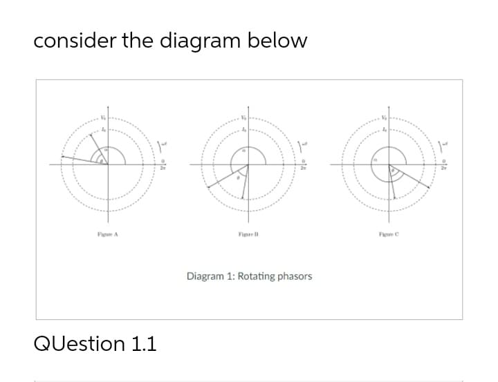
Transcribed Image Text:consider the diagram below
Pigure A
Figire
Feure C
Diagram 1: Rotating phasors
QUestion 1.1
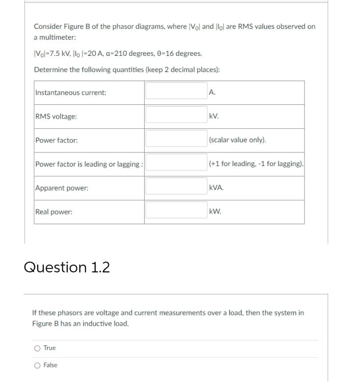
Transcribed Image Text:Consider Figure B of the phasor diagrams, where |Vol and |lol are RMS values observed on
a multimeter:
|Vol-7.5 kV. llo |-20 A, a-210 degrees, 0-16 degrees.
Determine the following quantities (keep 2 decimal places):
Instantaneous current:
A.
RMS voltage:
kV.
Power factor:
(scalar value only).
Power factor is leading or lagging :
(+1 for leading, -1 for lagging).
Apparent power:
kVA.
Real power:
kW.
Question 1.2
If these phasors are voltage and current measurements over a load, then the system in
Figure B has an inductive load.
True
False
Expert Solution
This question has been solved!
Explore an expertly crafted, step-by-step solution for a thorough understanding of key concepts.

Step by step
Solved in 2 steps with 1 images

Knowledge Booster


Learn more about
Need a deep-dive on the concept behind this application? Look no further. Learn more about this topic, electrical-engineering and related others by exploring similar questions and additional content below.Recommended textbooks for you
Power System Analysis and Design (MindTap Course …
Electrical Engineering
ISBN:
9781305632134
Author:
J. Duncan Glover, Thomas Overbye, Mulukutla S. Sarma
Publisher:
Cengage Learning
Power System Analysis and Design (MindTap Course …
Electrical Engineering
ISBN:
9781305632134
Author:
J. Duncan Glover, Thomas Overbye, Mulukutla S. Sarma
Publisher:
Cengage Learning