(d) 1.50 A Figure 3: Circuit for 50V IDa V, 3A Problems 6 and 7 Given the circuit of Figure 3, answer the following using nodal analysis Problem 6 The voltage v,is: (a) 40 V (b) 30 V (c) 25 V (d) 20 V Problem 7 The current is is: (a) 4 A (b) 2 А (c) 1 A (d) 0.5 A
(d) 1.50 A Figure 3: Circuit for 50V IDa V, 3A Problems 6 and 7 Given the circuit of Figure 3, answer the following using nodal analysis Problem 6 The voltage v,is: (a) 40 V (b) 30 V (c) 25 V (d) 20 V Problem 7 The current is is: (a) 4 A (b) 2 А (c) 1 A (d) 0.5 A

Delmar's Standard Textbook Of Electricity
7th Edition
ISBN:9781337900348
Author:Stephen L. Herman
Publisher:Stephen L. Herman
Chapter18: Resistive-inductive Parallel Circuits
Section: Chapter Questions
Problem 10PP: In an R-L parallel circuit, ET=240 volts, R=560, and XL=330. Find apparent power.

Related questions
Question
Do all URGENTLY
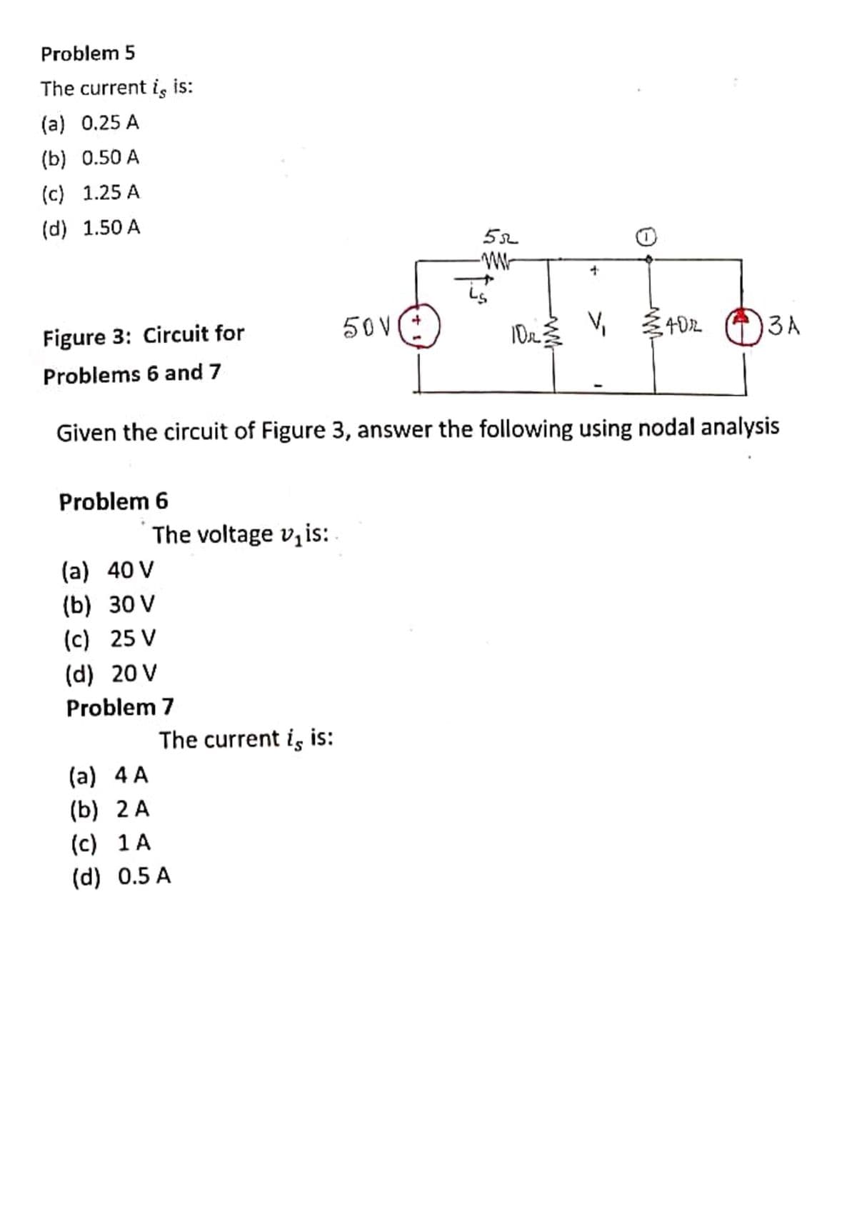
Transcribed Image Text:Problem 5
The current is is:
(a) 0.25 A
(b) 0.50 A
(c) 1.25 A
(d) 1.50 A
Figure 3: Circuit for
50V:
4D2
3A
Problems 6 and 7
Given the circuit of Figure 3, answer the following using nodal analysis
Problem 6
The voltage v,is:
(a) 40 V
(b) 30 V
(c) 25 V
(d) 20 V
Problem 7
The current is is:
(a) 4 A
(b) 2 A
(c) 1 A
(d) 0.5 A
Expert Solution
This question has been solved!
Explore an expertly crafted, step-by-step solution for a thorough understanding of key concepts.

This is a popular solution!

Trending now
This is a popular solution!

Step by step
Solved in 3 steps with 3 images

Knowledge Booster


Learn more about
Need a deep-dive on the concept behind this application? Look no further. Learn more about this topic, electrical-engineering and related others by exploring similar questions and additional content below.Recommended textbooks for you
Delmar's Standard Textbook Of Electricity
Electrical Engineering
ISBN:
9781337900348
Author:
Stephen L. Herman
Publisher:
Cengage Learning
Delmar's Standard Textbook Of Electricity
Electrical Engineering
ISBN:
9781337900348
Author:
Stephen L. Herman
Publisher:
Cengage Learning