(d) Compute the current from a to b through a 40 “load" resistor connected to the terminals. (e) What value of the load resistance should you avoid? Why? (f) Compute the power delivered by a 12V source connected to the terminals, + at a.
(d) Compute the current from a to b through a 40 “load" resistor connected to the terminals. (e) What value of the load resistance should you avoid? Why? (f) Compute the power delivered by a 12V source connected to the terminals, + at a.

Introductory Circuit Analysis (13th Edition)
13th Edition
ISBN:9780133923605
Author:Robert L. Boylestad
Publisher:Robert L. Boylestad
Chapter1: Introduction
Section: Chapter Questions
Problem 1P: Visit your local library (at school or home) and describe the extent to which it provides literature...

Related questions

Question
Hello, I am looking for help regarding parts D-F, as stated below the current is assumed clockwise, please show all work for understanding, thank you :)
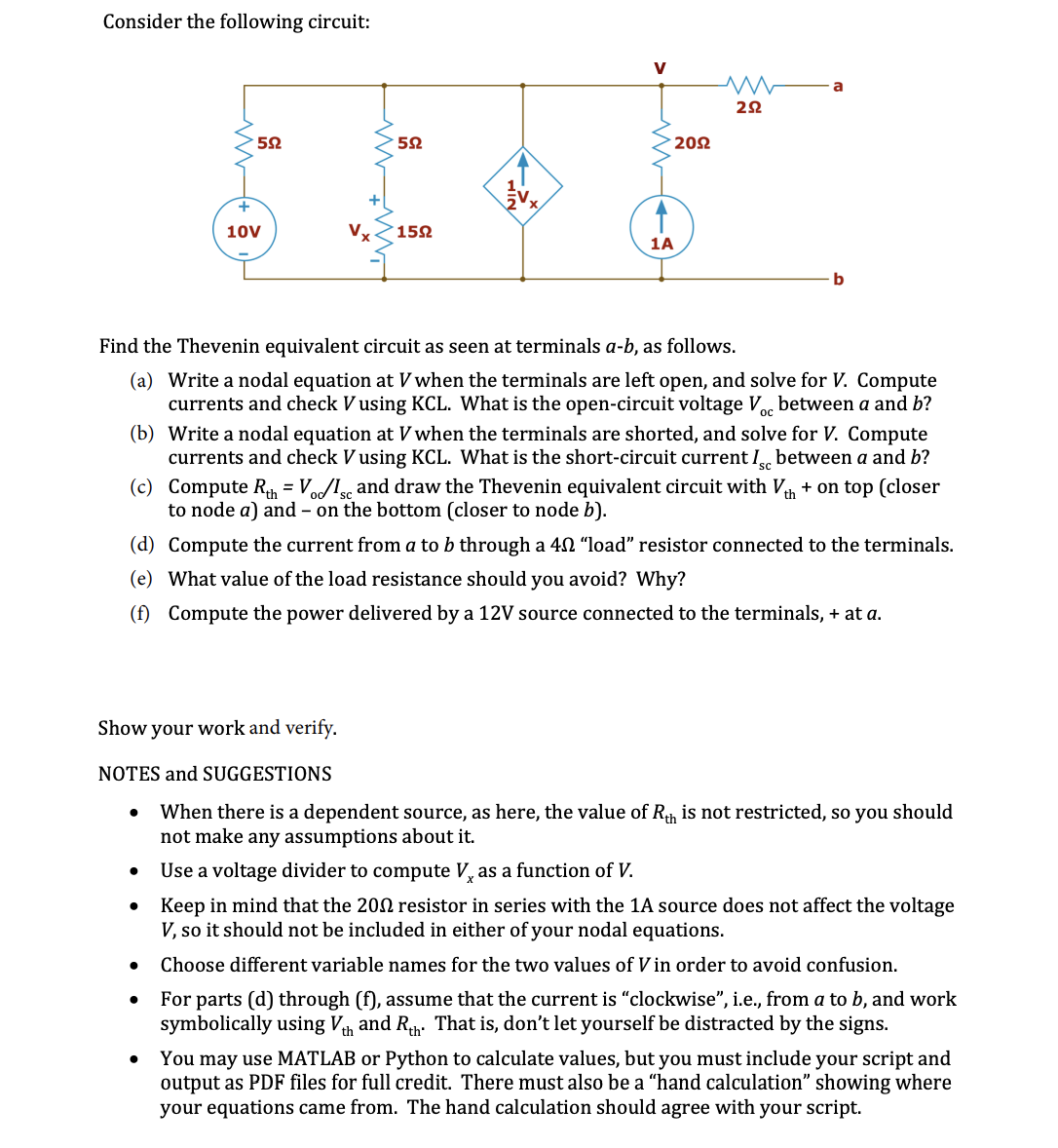
Transcribed Image Text:Consider the following circuit:
V
a
202
10V
Vx
152
1A
b
Find the Thevenin equivalent circuit as seen at terminals a-b, as follows.
(a) Write a nodal equation at V when the terminals are left open, and solve for V. Compute
currents and check V using KCL. What is the open-circuit voltage V, between a and b?
(b) Write a nodal equation at V when the terminals are shorted, and solve for V. Compute
currents and check V using KCL. What is the short-circuit current I between a and b?
sc
(c) Compute R, = Vo/l, and draw the Thevenin equivalent circuit with V + on top (closer
to node a) and – on the bottom (closer to node b).
(d) Compute the current from a to b through a 40 "load" resistor connected to the terminals.
(e) What value of the load resistance should you avoid? Why?
(f) Compute the power delivered by a 12V source connected to the terminals, + at a.
Show your work and verify.
NOTES and SUGGESTIONS
When there is a dependent source, as here, the value of Rh is not restricted, so you should
not make any assumptions about it.
Use a voltage divider to compute V, as a function of V.
Keep in mind that the 202 resistor in series with the 1A source does not affect the voltage
V, so it should not be included in either of your nodal equations.
Choose different variable names for the two values of V in order to avoid confusion.
For parts (d) through (f), assume that the current is "clockwise", i.e., from a to b, and work
symbolically using Vh and Rh. That is, don't let yourself be distracted by the signs.
You may use MATLAB or Python to calculate values, but you must include your script and
output as PDF files for full credit. There must also be a "hand calculation" showing where
your equations came from. The hand calculation should agree with your script.
Expert Solution
Step 1

Step by step
Solved in 2 steps with 3 images

Knowledge Booster


Learn more about
Need a deep-dive on the concept behind this application? Look no further. Learn more about this topic, electrical-engineering and related others by exploring similar questions and additional content below.Recommended textbooks for you
Introductory Circuit Analysis (13th Edition)
Electrical Engineering
ISBN:
9780133923605
Author:
Robert L. Boylestad
Publisher:
PEARSON

Delmar's Standard Textbook Of Electricity
Electrical Engineering
ISBN:
9781337900348
Author:
Stephen L. Herman
Publisher:
Cengage Learning

Programmable Logic Controllers
Electrical Engineering
ISBN:
9780073373843
Author:
Frank D. Petruzella
Publisher:
McGraw-Hill Education
Introductory Circuit Analysis (13th Edition)
Electrical Engineering
ISBN:
9780133923605
Author:
Robert L. Boylestad
Publisher:
PEARSON
Delmar's Standard Textbook Of Electricity
Electrical Engineering
ISBN:
9781337900348
Author:
Stephen L. Herman
Publisher:
Cengage Learning
Programmable Logic Controllers
Electrical Engineering
ISBN:
9780073373843
Author:
Frank D. Petruzella
Publisher:
McGraw-Hill Education

Fundamentals of Electric Circuits
Electrical Engineering
ISBN:
9780078028229
Author:
Charles K Alexander, Matthew Sadiku
Publisher:
McGraw-Hill Education

Electric Circuits. (11th Edition)
Electrical Engineering
ISBN:
9780134746968
Author:
James W. Nilsson, Susan Riedel
Publisher:
PEARSON

Engineering Electromagnetics
Electrical Engineering
ISBN:
9780078028151
Author:
Hayt, William H. (william Hart), Jr, BUCK, John A.
Publisher:
Mcgraw-hill Education,