I Review | Constant Learning Goal: In this tutorial, you will practice the calculation of power in circuits containing loads, including the effects of non- ideal transmission lines, and practice how to improve the power factor for an entire system. Part A - Power and power factor for parallel loads I Consider the two loads in the circuit in (Figure 1). Load #1 (L1) absorbs S = 57 kVA at a leading power factor of pfi = 0.57. Load #2 (L2) absorbs S2 = 56 kVA at a lagging power factor of pf2 = 0.71. Use this information to calculate the real (P) and reactive (Q) power provided by the V, = 300 V-rms 60 Hz source and its power factor (pf). Many appliances (e.g., hair dryers, coffee makers, and refrigerators) and industrial loads are powered by AC sources. The ability to be able to calculate their power needs is important in a number of situations. Before completing this tutorial, make sure you are familiar with the relationships between average, reactive, and apparent power and the power factor. Express your answers numerically to three significant figures separated by commas. • View Available Hint(s) VO AEO !t vec P, Q. pf = kW. KVAR, no unit Submit Part B - Power for a parallel load with a transmission line impedance Consider the circuit in (Figure 2). The load (L1) absorbs P = 33 W and Q = 23 VAR of power. Use this information to calculate complex power provided by the source if the voltage across the load is V, = 475 V-rms 60 Hz source and the impedance of the transmission line is 0.030 + j(-0.020) N. Figure 1 of 2 > Express your answer in rectangular complex form to three significant figures. • View Available Hint(s) Va AEo !t vec ? S = VA V() L1 L2 Submit
I Review | Constant Learning Goal: In this tutorial, you will practice the calculation of power in circuits containing loads, including the effects of non- ideal transmission lines, and practice how to improve the power factor for an entire system. Part A - Power and power factor for parallel loads I Consider the two loads in the circuit in (Figure 1). Load #1 (L1) absorbs S = 57 kVA at a leading power factor of pfi = 0.57. Load #2 (L2) absorbs S2 = 56 kVA at a lagging power factor of pf2 = 0.71. Use this information to calculate the real (P) and reactive (Q) power provided by the V, = 300 V-rms 60 Hz source and its power factor (pf). Many appliances (e.g., hair dryers, coffee makers, and refrigerators) and industrial loads are powered by AC sources. The ability to be able to calculate their power needs is important in a number of situations. Before completing this tutorial, make sure you are familiar with the relationships between average, reactive, and apparent power and the power factor. Express your answers numerically to three significant figures separated by commas. • View Available Hint(s) VO AEO !t vec P, Q. pf = kW. KVAR, no unit Submit Part B - Power for a parallel load with a transmission line impedance Consider the circuit in (Figure 2). The load (L1) absorbs P = 33 W and Q = 23 VAR of power. Use this information to calculate complex power provided by the source if the voltage across the load is V, = 475 V-rms 60 Hz source and the impedance of the transmission line is 0.030 + j(-0.020) N. Figure 1 of 2 > Express your answer in rectangular complex form to three significant figures. • View Available Hint(s) Va AEo !t vec ? S = VA V() L1 L2 Submit

Introductory Circuit Analysis (13th Edition)
13th Edition
ISBN:9780133923605
Author:Robert L. Boylestad
Publisher:Robert L. Boylestad
Chapter1: Introduction
Section: Chapter Questions
Problem 1P: Visit your local library (at school or home) and describe the extent to which it provides literature...

Related questions

Question
Solve for parts A & C.

Transcribed Image Text:I Review | Constant
Learning Goal:
In this tutorial, you will practice the calculation of power in
circuits containing loads, including the effects of non-
ideal transmission lines, and practice how to improve the
power factor for an entire system.
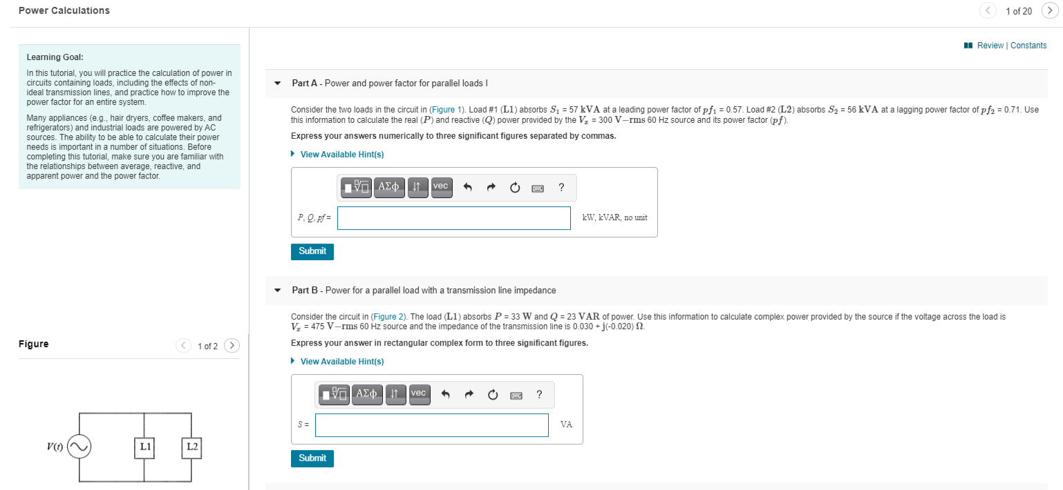
Part A - Power and power factor for parallel loads I
Consider the two loads in the circuit in (Figure 1). Load #1 (L1) absorbs S = 57 kVA at a leading power factor of pfi = 0.57. Load #2 (L2) absorbs S2 = 56 kVA at a lagging power factor of pf2 = 0.71. Use
this information to calculate the real (P) and reactive (Q) power provided by the V, = 300 V-rms 60 Hz source and its power factor (pf).
Many appliances (e.g., hair dryers, coffee makers, and
refrigerators) and industrial loads are powered by AC
sources. The ability to be able to calculate their power
needs is important in a number of situations. Before
completing this tutorial, make sure you are familiar with
the relationships between average, reactive, and
apparent power and the power factor.
Express your answers numerically to three significant figures separated by commas.
• View Available Hint(s)
VO AEO !t vec
P, Q. pf =
kW. KVAR, no unit
Submit
Part B - Power for a parallel load with a transmission line impedance
Consider the circuit in (Figure 2). The load (L1) absorbs P = 33 W and Q = 23 VAR of power. Use this information to calculate complex power provided by the source if the voltage across the load is
V, = 475 V-rms 60 Hz source and the impedance of the transmission line is 0.030 + j(-0.020) N.
Figure
1 of 2 >
Express your answer in rectangular complex form to three significant figures.
• View Available Hint(s)
Va AEo !t vec
?
S =
VA
V()
L1
L2
Submit
Expert Solution
This question has been solved!
Explore an expertly crafted, step-by-step solution for a thorough understanding of key concepts.

This is a popular solution!

Trending now
This is a popular solution!

Step by step
Solved in 4 steps with 12 images

Knowledge Booster


Learn more about
Need a deep-dive on the concept behind this application? Look no further. Learn more about this topic, electrical-engineering and related others by exploring similar questions and additional content below.Recommended textbooks for you
Introductory Circuit Analysis (13th Edition)
Electrical Engineering
ISBN:
9780133923605
Author:
Robert L. Boylestad
Publisher:
PEARSON

Delmar's Standard Textbook Of Electricity
Electrical Engineering
ISBN:
9781337900348
Author:
Stephen L. Herman
Publisher:
Cengage Learning

Programmable Logic Controllers
Electrical Engineering
ISBN:
9780073373843
Author:
Frank D. Petruzella
Publisher:
McGraw-Hill Education
Introductory Circuit Analysis (13th Edition)
Electrical Engineering
ISBN:
9780133923605
Author:
Robert L. Boylestad
Publisher:
PEARSON
Delmar's Standard Textbook Of Electricity
Electrical Engineering
ISBN:
9781337900348
Author:
Stephen L. Herman
Publisher:
Cengage Learning
Programmable Logic Controllers
Electrical Engineering
ISBN:
9780073373843
Author:
Frank D. Petruzella
Publisher:
McGraw-Hill Education

Fundamentals of Electric Circuits
Electrical Engineering
ISBN:
9780078028229
Author:
Charles K Alexander, Matthew Sadiku
Publisher:
McGraw-Hill Education

Electric Circuits. (11th Edition)
Electrical Engineering
ISBN:
9780134746968
Author:
James W. Nilsson, Susan Riedel
Publisher:
PEARSON

Engineering Electromagnetics
Electrical Engineering
ISBN:
9780078028151
Author:
Hayt, William H. (william Hart), Jr, BUCK, John A.
Publisher:
Mcgraw-hill Education,