D En D | Next state of Q En 0 X No change 1 0Q= 0; reset state 1 1Q= 1; set state %3D (a) Logic diagram (b) Function table
D En D | Next state of Q En 0 X No change 1 0Q= 0; reset state 1 1Q= 1; set state %3D (a) Logic diagram (b) Function table

Chapter22: Sequence Control
Section: Chapter Questions
Problem 6SQ: Draw a symbol for a solid-state logic element AND.

Related questions
Question
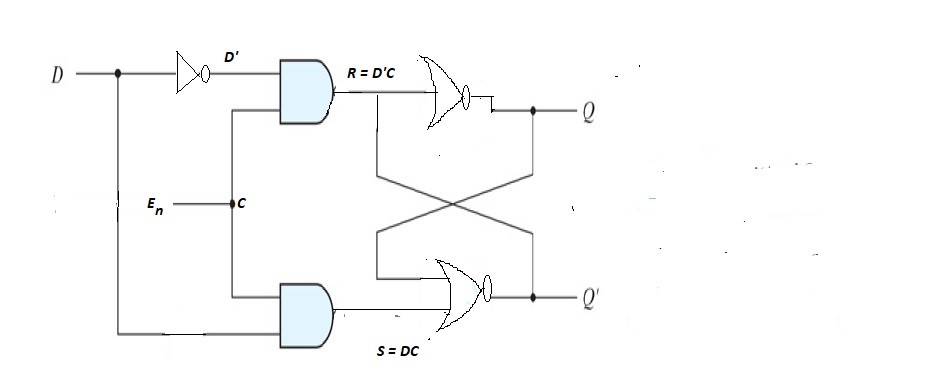
The D latch of Fig. 5.6 is constructed with four NAND gates and an inverter. Consider the following three other ways for obtaining a D latch. In each case, draw the logic diagram and verify the circuit operation. Use NOR gates for the SR latch part and AND gates for the other two. An inverter may be needed.

Transcribed Image Text:D
En D | Next state of Q
En
0 X No change
1 0Q= 0; reset state
1 1Q= 1; set state
%3D
(a) Logic diagram
(b) Function table
Expert Solution
Step 1
Solution-
Function table-
En D Next State of Q
0 x No change
1 0 0; Reset state
1 1 1 ; Set state

Step by step
Solved in 2 steps with 1 images

Knowledge Booster


Learn more about
Need a deep-dive on the concept behind this application? Look no further. Learn more about this topic, electrical-engineering and related others by exploring similar questions and additional content below.Recommended textbooks for you