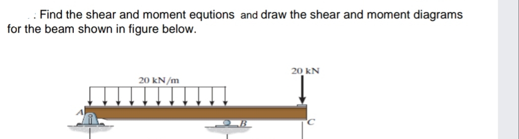
d the shear and am shown in fig


Q: 2. Without writing the shear and diagrams. 50 KN 20 KN A B
A:
Q: Required information Consider a solid shaft of 18-mm diameter. Determine the maximum shearing stress…
A: Given: The diameter of the shaft is d=18 mm. The power transmitted by the shaft is P=3.4 kW. The…
Q: The shear diagram will jump downward if the _________________ a. Total weight is applied b.…
A: To Fill in the blank for the question where The shear diagram will jump downward Option given are…
Q: VQ/lt can not be used to calculate the shear stress distribution of a
A: Given, It is asked about the validation of shear stress distribution for given area
Q: derive shear and moment equations
A:
Q: A cross section of the beam as shown in Fig. If subjected to a maximum vertical shearing force of 60…
A: When there is a variation in bending moment, shear stress produces in a beam. Shear stress at any…
Q: 1. Find the maximum bending stress - and find the factor of safety 2. find with using the…
A: In this problem, it is asking only maximum bending stress, maximum shear stress along with factor of…
Q: Do the stress concentrations exist on a shaft?
A: Stress concentration is increase in stress at particular point where stress is more because of hole…
Q: (a) Using the Castigliano method, derive an expression for the vertical bend in D. (b) Determine the…
A: (a) The diagram of the beam with support reactions and an imaginary load Q at point D is given as,…
Q: Calculate and sketch the shear and bending moment diagrams.
A: The free-body diagram of the given loading beam can be drawn as below, Here, RA and RD are the…
Q: thin rectangular plate is uniformly deformed as shown below. Compute the shearing strain at P…
A: Solution is attached below:
Q: If the beam has a solid rectangular cross-section, what does the shear formula become?
A:
Q: shear and moment diagram and calculate the maximum shear and moment
A:
Q: without writing shear equations, draw the shear diagrams for the Beam loaded as shown in Fig.
A:
Q: A circular shape blank will be cut of 100+ 10 N mm diameter from a strip of 2.8+ 100 mm with a…
A: given diameter of circular blank to be cut, db=101 mmstrip thickness, t=2.9 mmclearnace, C=0.25…
Q: Calculate the force required to shear a 0.7" dia. hole through a 0.16" thick piece of yellow brass.…
A: Given data: The diameter of the hole is d = 0.7 in. The thickness of the plate is t = 0.16 in. The…
Q: w through horizontal wrought pe: v= 3 m/s
A:
Q: Draw the shear and moment diagrams for the loaded beam. After you have the diagrams, answer the…
A: The expression obtained by taking summation of forces along y-axis is, ∑Fy=0Fy-P-7 kN/m×10 m2=0…
Q: "4₂ A two celled tube with wall thickness 0.5 mm is subjected to a torque of 10 N.m as shown in…
A: Given data: t = 0.5 mm = 0.0005 m two cell tubes with square shape. their side (a) =50 mm = 0.05 m…
Q: Home Work: 1. As shown in figure below, a hole is to be punched out of a plate having an ultimate…
A:
Q: Derive the expression of shear plane angle. Draw and mention all corresponding angle required for…
A:
Q: Prove the formula for Hoop stress and longitudinal stress and also explain poisson ratio.
A: Given Data⇒ Hoop Stress Longitudinal Stress Poisson ratio
Q: shear force and the bending mome in the Fig and sketch the shear and 500 N/m
A: GIVEN:
Q: Prove that the most efficient triangular section is the one with a 90° vertex angle.
A: Area of the triangular section, A=my(y)=y2tanϕ Wetted perimeter, P=2y01+m2=2ysecϕ
Q: The 70-mm diameter solid shaft carries the torsional loadings shown. Calculate the maximum shearing…
A:
Q: = Draw the shear and bending moment diagram, where p 8 kip.
A:
Q: @, Drow the shear und mo ment diagram for the heam Shoun in fig.use area loud aud Shear G Ikwlm
A: Given: A beam
Q: Draw the shear and moment diagram for the beam shown in fig
A: Consider the free body diagram as shown below for the given system.
Q: Q 3: The smallest diameter bolt that can be used in the clevis shown in .figure is.. if P= 200 kN.…
A: Given, Applied force = P = 200 kN = 2 x 10⁵ N Shear strength of bolt = τ = 300 MPa Let us say…
Q: 8 mm x 36 mm Calculate the shear
A: for solution refer below images.
Q: A flange coupling having 6 bolts, each 18 mm in diameter, is used to transfer the power of a 75-mm…
A:
Q: Derive the formula for the maximum shearing stress due to bending if the the cross section is a…
A: Derive the formula for the maximum shearing stress due to bending
Q: Calculate the maximum shear.
A:
Q: Find the shear centre of the circular thickness t, as shown below.
A:
Q: At a given 7 locations/sections (0,1,2,3,4,5,6) on a beam of uniform I-section, the beam is…
A: Given: Shear force=100 kN
Q: Given the figure with its V = 45 kN; bf = 9: mm; bw = 20 mm; d = 115 mm; tf = 28. What is the…
A:
Q: in the figure, the vertical shear is 45 etermine the shearing stress of poir
A:
Q: Determine shear
A: Given; A motor driving a solid circular steel shaft transmits; Power= 50 kWSpeed,N= 500 rpmIf the…
Q: What is the Shear Force,V?
A: To define: The shear force. Concept used: Shear force: Shear force is an internal force in any…
Q: Timet 60 kH 30KN DROW the shear and moment diagram with complete sokrtion Im
A:
Q: 2. Draw the complete shearing force and bending moment diagrams. 10 K 10 K 3 ft 8 ft 3 ft
A:
Q: A circular shape blank will be cut of 100 mm diameter from a strip of 2.8 mm with a clearance value…
A: Given data as per questiondiameter of blank =100 mmstrip thickness=2.8 mmclearance value=0.25…
Q: Using the graphical method draw the complete shearing and bending moment diagrams for the beam shown…
A:
Q: Consider the forces acting on the chip during an orthogonal cutting as shown in Figure 3. The…
A:
Q: A metal cutter is used to chop metal sheets. The length of the metal sheets is 100 width of the…
A:
Q: hese garden shears were manufactured using an inferior material. Using a loading of 50 lb applied…
A: Consider the cross section of the shear is square shape of aspects 50 mm x 20mm Assuming the length…
Q: on of shear force and d drawing the shear beam. moments at points A 8kN
A:

Step by step
Solved in 3 steps with 3 images


- Two identical, simply supported beams AB and CD are placed so that they cross each other at their midpoints (sec figure). Before the uniform load is applied, the beams just touch each other at the crossing point. Determine the maximum bending moments (mab)max* and (MCD)max beams AB and CD, respectively, due to the uniform load if the intensity of the load is q = 6.4 kN/m and the length of each beam is L = 4 m..20 Determine the plastic moment Mpfor beam having the cross section shown in the figure ey=210 MPa.A two-axle carriage that is part of an over head traveling crane in a testing laboratory moves slowly across a simple beam AB (sec figure). The load transmitted to the beam from the front axle is 2200 lb and from the rear axle is 3800 lb. The weight of the beam itself may be disregarded. Determine the minimum required section modulus S for the beam if the allowable bending stress is 17,0 ksi, the length of the beam is 18 ft, and the wheelbase of the carriage is 5 ft. Select the most economical I-beam (S shape) from Table F-2(a), Appendix F.
- A rectangular beam with semicircular notches, as shown in part b of the figure, has dimensions h = 0,88 in. and h1 = 0.80 in. The maximum allowable bending stress in the metal beam is emax = 60 ksi, and the bending moment is M = 600 lb-in. Determine the minimum permissible width bminof the beam.A wood box beam is constructed of two 260 mm × 50 mm boards and two 260 mm × 25 mm boards (sec figure). The boards are nailed at a longitudinal spacing. b = 100 mm. If each nail has an allowable shear force F = 1200 N. what is the maximum allowable shear force Vmax?A hollow steel box beam has the rectangular cross section shown in the figure. Determine the maximum allowable shear force K that may act on the beam if the allowable shear stress is 36 MPa. c
- The cross section of a sand wie h beam consisting of aluminum alloy faces and a foam core is shown in the figure. The width b of the beam is 8.0 in, the thickness I of the faces is 0.25 in., and the height hcof the core is 5.5 in. (total height h = 6.0 in). The moduli of elasticity are 10.5 × 10⁶ psi for the aluminum faces and 12.000 psi for the foam core. A bending moment M = 40 kip-in. acts about the z axis. Determine the maximum stresses in the faces and the core using (a) the general theory for composite beams and (b) the approximate theory for sandwich beams.The hollow box beam shown in the figure is subjected to a bending moment M of such magnitude that the flanges yield but the webs remain linearly elastic. (a) Calculate the magnitude of the moment M if the dimensions of the cross section are A = 15 in., A] = 12.75 in., h = 9 in., and ey =7.5 in. Also, the yield stress is eY = 33 ksi. (b) What percent of the moment M is produced by the elastic core?Determine the fixed-end moments (MAand MB) and fixed-end forces (R4and Rs) for a beam of length L supporting a triangular load of maximum intensity q0(see figure). Then draw the shear-force and bending-moment diagrams, labeling all critical ordinates.
- A frame ABCD is constructed of steel wide-flange members (W8 x 21; E = 30 x ID6 psi) and subjected to triangularly distributed loads of maximum intensity q0acting along the vertical members (see figure). The distance between supports is L = 20 ft and the height of the frame is h = 4 ft. The members are rigidly connected at B and C. Calculate the intensity of load q0 required to produce a maximum bending moment of 80 kip-in. in the horizontal member BC. If the load q0 is reduced to one-half of the value calculated in part (a), what is the maximum bending moment in member BC? What is the ratio of this moment to the moment of 80 kip-in. in part (a)?A steel beam is built up from a W 410 × 85 wide flange beam and two 180 mm X 9 mm cover plates (see figure). The allowable load in shear on each bolt is 9.8 kN. What is the required bolt spacing s in the longitudinal direction if the shear force V = 110 kN Noie: Obtain the dimensions and moment of inertia of the W shape from Table F-l(b).Two W 310 × 74 Steel wide-flange beams are bolted together to form a built-up beam as shown in the figure. What is the maximum permissible bolt spacing s if the shear force V = 80 kN and the allowable load in shear on each bolt is F = 13.5 kN. Note: Obtain the dimensions and properties of the W shapes from Table F-l(b).