
Mechanics of Materials (MindTap Course List)
9th Edition
ISBN: 9781337093347
Author: Barry J. Goodno, James M. Gere
Publisher: Cengage Learning
expand_more
expand_more
format_list_bulleted
Videos
Textbook Question
Chapter 6, Problem 6.10.20P
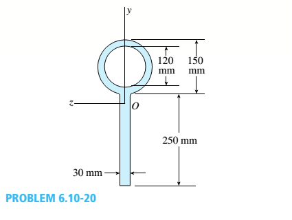
.20 Determine the plastic moment Mpfor beam having the cross section shown in the figure ey=210 MPa.
Expert Solution & Answer
Want to see the full answer?
Check out a sample textbook solution
Students have asked these similar questions
The beam is shown in Fig. a has a cross-sectional area in the shape of a channel, Fig. b. Determine the maximum bending stress that occurs in the beam at section a–a.
Determine the displacement at point C on the steel overhanging beam shown in Fig. a. Take Est = 29(103) ksi, I = 125 in4.
Now consider the same beam when a 60-inch-long rod is added at mid-span. The rod’s crosssection area is 0.50 in2 . Find the axial stress in the rod, draw the shear and moment diagrams forthe beam, and find the maximum stress in the beam.
Chapter 6 Solutions
Mechanics of Materials (MindTap Course List)
Ch. 6 - A composite beam is constructed using a steel...Ch. 6 - A wood beam is strengthened using two steel plates...Ch. 6 - A composite beam consisting of fiberglass faces...Ch. 6 - A wood beam with cross-sectional dimensions 200 mm...Ch. 6 - A hollow box beam is constructed with webs of...Ch. 6 - A r o lukI f/frm f «m t ub e of ou t sid e d ia...Ch. 6 - A beam with a guided support and 10-ft span...Ch. 6 - A plastic-lined steel pipe has the cross-sectional...Ch. 6 - The cross section of a sand wie h beam consisting...Ch. 6 - The cross section of a sandwich beam consisting of...
Ch. 6 - A bimetallic beam used in a temperature-control...Ch. 6 - A simply supported composite beam 3 m long carries...Ch. 6 - A simply supported wooden I-beam with a 12-ft span...Ch. 6 - -14 A simply supported composite beam with a 3.6 m...Ch. 6 - -15 A composite beam is constructed froma wood...Ch. 6 - A wood beam in a historic theater is reinforced...Ch. 6 - Repeat Problem 6.2-1 but now assume that the steel...Ch. 6 - Repeat Problem 6.2-17 but now use a...Ch. 6 - A sandwich beam having steel faces enclosing a...Ch. 6 - A wood beam 8 in. wide and 12 in. deep (nominal...Ch. 6 - A simple beam of span length 3.2 m carries a...Ch. 6 - A simple beam that is 18 ft long supports a...Ch. 6 - The composite beam shown in the figure is simply...Ch. 6 - The cross section of a beam made of thin strips of...Ch. 6 - Consider the preceding problem if the beam has...Ch. 6 - A simple beam thai is IS ft long supports a...Ch. 6 - The cross section of a composite beam made of...Ch. 6 - A beam is constructed of two angle sections, each...Ch. 6 - The cross section of a bimetallic strip is shown...Ch. 6 - A W 12 x 50 steel wide-flange beam and a segment...Ch. 6 - A reinforced concrete beam (see figure) is acted...Ch. 6 - A reinforced concrete T-beam (see figure) is acted...Ch. 6 - A reinforced concrete slab (see figure) is...Ch. 6 - A wood beam reinforced using two channels is...Ch. 6 - A wood beam reinforced by an aluminum channel...Ch. 6 - A beam with a rectangular cross section supports...Ch. 6 - A wood beam with a rectangular cross section (see...Ch. 6 - Solve the preceding problem for the following...Ch. 6 - A simply supported wide-flange beam of span length...Ch. 6 - Solve the preceding problem using the fol...Ch. 6 - A wood cantilever beam with a rectangular cross...Ch. 6 - Solve the preceding problem for a cantilever beam...Ch. 6 - A 2-m-long cantilever beam is constructed using a...Ch. 6 - A wood beam AB with a rectangular cross section (4...Ch. 6 - A steel beam of I-section (see figure) is simply...Ch. 6 - A cantilever beam with a wide-flange cross section...Ch. 6 - Solve the preceding problem using a W 310 x 129...Ch. 6 - A cantilever beam of W 12 × 14 section and length...Ch. 6 - A cantilever beam built up from two channel...Ch. 6 - A built-Lip I-section steel beam with channels...Ch. 6 - Repeat Problem 6.4-14 but use the configuration of...Ch. 6 - A beam with a channel section is subjected to a...Ch. 6 - A beam with a channel section is subjected to a...Ch. 6 - An angle section with equal legs is subjected to a...Ch. 6 - An angle section with equal legs is subjected to a...Ch. 6 - A beam made up all woun equal leg angles is...Ch. 6 - The Z-section of Example D-7 is subjected to M = 5...Ch. 6 - The cross section of a steel beam is constructed...Ch. 6 - The cross section of a steel beam is shown in the...Ch. 6 - A beam with a semicircular cross section of radius...Ch. 6 - .10 A built-up bourn supporting a condominium...Ch. 6 - Asteelpost (E = 30 × 106 psi) having thickness t =...Ch. 6 - A C 200 x 17.1 channel section has an angle with...Ch. 6 - A cold-formed steel section is made by folding a...Ch. 6 - A simple beam with a W 10 x 30 wide-flange cross...Ch. 6 - Solve the preceding problem for a W 250 × 44.8...Ch. 6 - A beam of wide-flange shape, W 8 x 28, has the...Ch. 6 - Solve the preceding problem for a W 200 × 41,7...Ch. 6 - Calculate the distance e from the cent crime of...Ch. 6 - Calculate the distance e from the centerline of...Ch. 6 - The cross section of an unbalanced wide-flange...Ch. 6 - The cross section of an unbalanced wide-flange...Ch. 6 - The cross section of a channel beam with double...Ch. 6 - The cross section of a slit circular tube of...Ch. 6 - The cross section of a slit square tube of...Ch. 6 - The cross section of a slit rectangular tube of...Ch. 6 - A U-shaped cross section of constant thickness is...Ch. 6 - Derive the following formula for the distance e...Ch. 6 - Derive the following formula for the distance e...Ch. 6 - The cross section of a sign post of constant...Ch. 6 - A cross section in the shape of a circular arc of...Ch. 6 - Determine the shape factor f for a cross section...Ch. 6 - (a) Determine the shape factor/for a hollow...Ch. 6 - A propped cantilever beam of length L = 54 in....Ch. 6 - A steel beam of rectangular cross section is 40 mm...Ch. 6 - .5 Calculate the shape factor j for the...Ch. 6 - Solve the preceding problem for a wide-flange beam...Ch. 6 - Determine the plastic modulus Z and shape...Ch. 6 - Prob. 6.10.8PCh. 6 - Prob. 6.10.9PCh. 6 - Prob. 6.10.10PCh. 6 - A hollow box beam with height h = 16 in,, width h...Ch. 6 - Solve the preceding problem for a box beam with...Ch. 6 - A hollow box beam with height h = 9.5 in., inside...Ch. 6 - Solve the preceding problem for a box beam with...Ch. 6 - The hollow box beam shown in the figure is...Ch. 6 - Prob. 6.10.16PCh. 6 - Prob. 6.10.17PCh. 6 - A singly symmetric beam with a T-section (see...Ch. 6 - A wide-flange beam with an unbalanced cross...Ch. 6 - .20 Determine the plastic moment Mpfor beam having...
Knowledge Booster


Learn more about
Need a deep-dive on the concept behind this application? Look no further. Learn more about this topic, mechanical-engineering and related others by exploring similar questions and additional content below.Similar questions
- The composite beam in Fig. a is made of wood and reinforced with a steel strap located on its bottom side. If the beam is subjected to a bending moment of M = 2 kN # m, determine the normal stress at points B and C. Take Ew = 12 GPa and Est = 200 GPa.arrow_forwardA rectangular beam 80 mm x 40 mm is 3m long and simply supported at the ends. It carries a load of 1 kN at the mid-span. Determine the maximum bending stress induced in the beam.arrow_forwardDetermine the most critical point of the beam shown below in terms of bending moment.arrow_forward
- Determine the ratios of the weights of four beams that have same length.are made of the same material,are subjected to the same lmaximum bending moment,and have the same maximum bending stress if their cross sections are (I) a rectangle with height equal to twice the width,(2) a square,(3) a circle , and (4) a pipe with outer diameter d and wall thickmess f = di% (see figures).arrow_forwardFor the beam shown below, determine the maximum bending stress in the beam. sketch thesection stress distribution.arrow_forwardA beam having a tee-shaped cross section is subjected to equal 13 kN-m bending moments, as shown. Assume bf = 95 mm, tf = 25 mm, d = 165 mm, tw = 40 mm. The cross-sectional dimensions of the beam are also shown. Determine(a) the centroid location (measured upward from the bottom), the moment of inertia about the z axis, and the controlling section modulus about the z axis.(b) the bending stress at point H (positive if tensile and negative if compressive).(c) the maximum bending stress (positive if tensile and negative if compressive) produced in the cross section.arrow_forward
- Draw the shear stress diagram and bending moment diagram for a beam with the free body diagram shown below. Identify the location of critical point(s) in the beam. Given AB = 0.5 m, BC = 0.6 mm, and CD = 0.5 m.arrow_forward1. Determine the maximum positive bending moment in the beam in kN-m. 2. Determine the maximum shear in kN. 3. Determine the location of Neutral Axis, in mm, from the top of the section. 4. Determine the location of the centroid, in mm, from the left of the section. 5. Determine the moment of inertia of the section in x106 mm4 . 6. Determine the moment capacity of the section, kN-m, if fbcap≤300 MPa. 7. Determine the maximum flexural stress experienced by the beam in MPa. 8. Determine the maximum shearing stress in MPa at Neutral Axis. 9. Determine the spacing of rivets in mm. 10. Determine the maximum flexural stress at 1 m from the support at D to E in MPa.arrow_forwardDerive the formula for the bending stress of a beam with a rectangular cross section and triangular cross secrion. Thank youarrow_forward
- An I section symmetrical beamhas 200mm wide flange and overall depth of 500mm. Each flange is 25mm thickand the web is 20mm thick. Determine the maximum bending moment that should be imposed in the sectionif the tensile or the compressive stressis not to exceed 40MN/m^2 and what percentage of the moment is resisted by flange or web?arrow_forwardFind the maximum bending stress in the rectangular wooden beam.arrow_forwardDetermine the slope at point B of the beam shown in Figure. EI is constant.arrow_forward
arrow_back_ios
SEE MORE QUESTIONS
arrow_forward_ios
Recommended textbooks for you
 Mechanics of Materials (MindTap Course List)Mechanical EngineeringISBN:9781337093347Author:Barry J. Goodno, James M. GerePublisher:Cengage Learning
Mechanics of Materials (MindTap Course List)
Mechanical Engineering
ISBN:9781337093347
Author:Barry J. Goodno, James M. Gere
Publisher:Cengage Learning
Mechanics of Materials Lecture: Beam Design; Author: UWMC Engineering;https://www.youtube.com/watch?v=-wVs5pvQPm4;License: Standard Youtube License