Derive an expression for the shear stress distribution in a beam of solid rectangular cross- section transmitting a vertical shear V.
Derive an expression for the shear stress distribution in a beam of solid rectangular cross- section transmitting a vertical shear V.

Mechanics of Materials (MindTap Course List)
9th Edition
ISBN:9781337093347
Author:Barry J. Goodno, James M. Gere
Publisher:Barry J. Goodno, James M. Gere
Chapter6: Stresses In Beams (advanced Topics)
Section: Chapter Questions
Problem 6.10.7P: Determine the plastic modulus Z and shape factor/for a W 12 x 14 wide-flange beam. Obtain the...

Related questions

Question
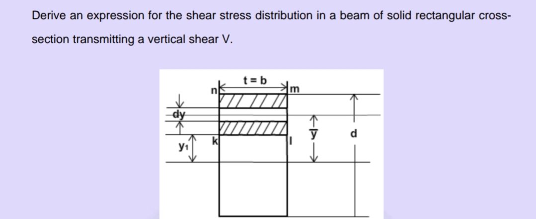
Transcribed Image Text:Derive an expression for the shear stress distribution in a beam of solid rectangular cross-
section transmitting a vertical shear V.
t = b
d
y1
Expert Solution
This question has been solved!
Explore an expertly crafted, step-by-step solution for a thorough understanding of key concepts.

This is a popular solution!

Trending now
This is a popular solution!

Step by step
Solved in 3 steps with 5 images

Knowledge Booster


Learn more about
Need a deep-dive on the concept behind this application? Look no further. Learn more about this topic, mechanical-engineering and related others by exploring similar questions and additional content below.Recommended textbooks for you
Mechanics of Materials (MindTap Course List)
Mechanical Engineering
ISBN:
9781337093347
Author:
Barry J. Goodno, James M. Gere
Publisher:
Cengage Learning
Mechanics of Materials (MindTap Course List)
Mechanical Engineering
ISBN:
9781337093347
Author:
Barry J. Goodno, James M. Gere
Publisher:
Cengage Learning