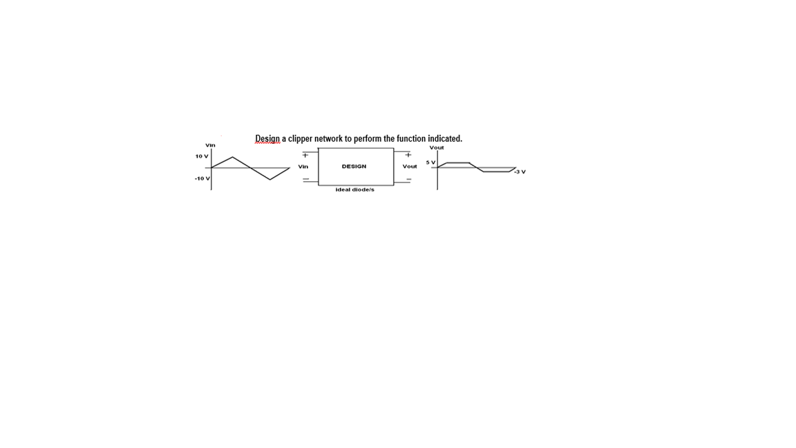
Design a clipper network to perform the function indicated. Vin Vout 10 v SV DESIGN Vout 10 Ideal diodeis


Q: ELECTRONICS LABORATORY, EXPERIMENT 3. tmA Load-line Analysis 1. (a) Using the characteristics of…
A: Dear students as per our guidelines we are supposed to answer only one question.Kindly repost other…
Q: (d) For a thermocouple device, determine the terminal voltage of the thermocouple with a=40µV/ºC if…
A: We need to find out terminal voltage for given temperature difference
Q: Sketch i0 and v01 for the network below for the input shown (Both diodes are Si. VD=0.7 V). Explain…
A: Here in this figure both diodes will never conduct because when we open diode testing then both…
Q: use the noode - votage method to Find the value of , No in the CirCuit of FiGibelow 80on vo You 50v
A:
Q: (a) Sketch the waveform of Vo for the given network. The diode in the network is Si based צמ 3k2 1kN…
A: fig: Given circuit From above circuit it is clear that diode is forward…
Q: assume that the diodde in the circuit diagram below is reversed, 1.sketch the output waveform (Vo)…
A: In positive half cycle, Si Diode will be On and Vout will be input voltage after subtracting Diode…
Q: For the series diode configuration of Fig. 213, determine VD, VR, and ID + VD ▼ IR Si Ip R 2.2 ΚΩ E…
A: The solution is given below
Q: Q1: For the circuit shown below, assuming V,= 10V: 1. Calculate the current in the diode (Ip). 1 kQ…
A: The semiconductor diode circuit shown in the question can be solved by finding the State ( ON or OFF…
Q: Q8/ Assuming Silicon diode, sketch v, i, va, and ia for the following network: + Vd
A: The solution can be achieved as follows.
Q: For the network below, determine the range of Vi that will maintain the load voltage at 8 V and not…
A: Given VZ=8 VRS=91 ΩRL=0.22 kΩPZmax=400 mW The minimum input voltage is given by…
Q: Find the power dissipated in the diode. * 2200 18V 21, 21.3kQ 10V
A:
Q: 6. If a varactor diode is to be connected at the red spot, where would its anode be placed? RT Vi, O…
A: As we know that the varactor diode always function in reverse biasing condition.
Q: For the following clipper network, analyze the circuit, show your solution and plot Vo(t) versus…
A:
Q: •plot * Use ideal diede model D * plot Vout vs Vin Vin R Vout
A: Explanation: An ideal diode is a diode that acts like a really perfect conductor while voltage is…
Q: Q3. In the circuit shown the diodes are ideal. (a) Find and sketch the transfer characteristic of…
A:
Q: H.W: For the series diode configuration of Fig. below, determine VD, VR3 and Ip. Si E 05V 1.2 ka v
A: here the silicon didoe is connected in series with the voltage source and the resistor
Q: C = 47 microF , RL = 1kOhm , Vs = 90cos2000t V Find the diode current in the one-time charging.
A: Given circuit: C=47 μFRL=1 kΩVs=90cos2000t V To find: The diode current in the one-time charging.
Q: Q3. In the circuit shown the diodes are ideal. (a) Find and sketch the transfer characteristic of…
A: Here we will for which value of input diode will on or off, according that we will decide the output…
Q: XProblem No.1 (PI). A fixed bias NPN BJT (Beta = 90) circuit is connected to a 16VDC supply with the…
A: Given: Brief description: In the above given question they have mentioned an analog discrete…
Q: R= 10 kn D2 D1 Vout V2= 4.3 V R,= 5 kn V,= 1.8 V (+ 6 sin(wt)
A: The Diode Clipper, also known as a Diode Limiter, is a wave shaping circuit that takes an input…
Q: QI/Calculate the de and ac resistance for the diode of Fig at a forward current of 10 mA and compare…
A: Solution: In the question they have mentioned the I/ V characteristics of practical diode. Vd…
Q: a. Determine VL, IL, and IR for the network of below if RL=180 ohms b. Repeat part (a) if RL=470…
A: Since you have posted the questions with multiple subpart so we are supposed to answer the 3…
Q: tch Vo for the network of Figure below and determine the dc voltage available. Ideal Diode Ideal…
A:
Q: A) what is the calculated Rin? B) Submit a plot for Vout as a function of Vin for varying Vin over 0…
A: As given in question , circuit diagram is On applying KCL at A ,…
Q: (i) In Fig.(a), calculate the load current, load voltage, load power, diode power, and total power.…
A: Note: We are authorized to answer the first question since the exact one wasn’t specified. Please…
Q: Q. If VEB = 1.8V. Find LED electric current and approximate collector voltage Vc. Vcc +5 V + VBB O…
A: The circuit diagram is, Determining the emitter voltage,
Q: 1. What is Iceo ? 2. List various operating regions of Transistor. 3. Suggest an electronic circuit…
A: Hello. Since you have posted multiple questions and not specified which question needs to be solved,…
Q: What is output value of the circuit below when input in negative half cycle, suppose Vi= 20 Vp.p,…
A:
Q: 1) Given the Zener diode regulator circuit below, a. Determine V, I, I, and I, for the network below…
A: Since we only answer up to 3 sub-parts, we’ll answer the first 3. Please resubmit the question and…
Q: For the series diode configuration of Fig. Q1 (b), determine Vp, Vr, and Ip + VD IR Si + ID + E X V…
A: As given diode is of Si cut in voltage for Si diode = 0.7 Volt So, VD =0.7 Volt ID =E-VDR…
Q: Q1/ In the circuit shown below, the zener diode used has the following specifications : Vz= 12 volt,…
A: According to KVL , voltages in closed loop is zero . let current from source is I , then KVL in…
Q: Rs 1kQ 16 Vs Vz= 5.1 V RL 16ohm
A:
Q: ) For the following circuit, answer the following questions given that : Vz = 10 V, Iz= 25 mA, IzK=…
A:
Q: Q. If V = 1.8V. BB Find LED electric current and approximate collector voltage Vc. Vcc +5 V + VBB O…
A: To calculate the LED current and approximately voltage VC. As there is no element connect across the…
Q: Q1/Calculate the de and ac resistance for the diode of Fig. at a forward current of 10 mA and…
A: Given : In the given question they have mentioned the current and voltage characteristics of the…
Q: Determine Vin(max) of the Zener diode circuit as shown below so that it can keep regulation.…
A: Zener diode is heavily doped semiconductor that conduct in forward and reverse direction. In forward…
Q: QI: If an averaging d.c. Ammeter is connected in series with the Zener diode of circuit -Amp? Fig.…
A:
Q: 100V Ideal diodes 2.2 k 2.2 ka 2.2 ka
A: The diode is ON when the voltage across anode is more than the cathode voltage. It is known as…
Q: ues Using complete model, if rd3202 for each diode, then Ip2 is equal to www si 3-6K2 15V 2.57mA…
A: Due to presence of 15v potential the only diode through which current ID2 is flowing will conduct…
Q: Sketch Vo for the network 100 V Ideal diodes -100 V 2.2 k2 2.2 k2 2.2 k2
A: The diode is ON when the voltage across anode is more than the cathode voltage. It is known as…
Q: From the circuit below, determine the current Iz flowing through the zener diode if RL is removed or…
A: Zener diode maintains constant voltage Vz across it when voltage Across zener diode exceeds Vz when…
Q: For the Zener diode network of figure below, if R = 1 kN, R̟ = 5 kl, V; = 24 V , Vz = 15 V, Pzm = 60…
A: Zener diode- A Zener diode is a semiconductor diode used to create a stable voltage reference or…
Q: QUESTION 6 • For the given circuit, sketch Vo and determine its equivalent the DC voltage. Idcal 22…
A:
Q: Kit One: 1 kQ For the circuit shown below, assuming Vs= 10V: 1. Calculate the current in the diode…
A: Given circuit, where, Vs = 10 V Assuming Diode is Si diode, so there is 0.7 V voltage drop across…
Q: H.W: For the series diode configuration of Fig. below, determine Vp, VR, and Ip. E 0SV
A:
Q: Draw the load line of the following dc-biased silicon transistors. ß= 100 Ic | Re=2 ΚΩ Rg = 100 kn…
A:
Q: What is output value of the circuit below when input in negative half cycle, suppose Vi= 20 Vp.p,…
A:
Q: For the diode circuit of the figure below: 1. Determine v, and sketch its waveform for at least 4…
A:

Step by step
Solved in 4 steps with 4 images

- image483Q 3 Bring out the advantages and disadvantages of microwave tube devices andsemiconductor devices.What are the most common types of microwave diodes and transistors in use give theirbasic features features and applications?What are the most common types of microwave ICs? Give details of the circuit elementsand applicationsShow the Common Emitter amplified output when sinusoidal 100Hz signal is applied at the input capacitor. Plz show the circuit diagram
- Using IC that is approximately equal to IE. Determine the value of emitter voltage VE, when VCC=17V, R4=1441 ohms, R3=242 ohms, VC=9 V and R2=5256ohm R5=303 ohmFill in the missing parameter values for the BJT in the table if rx = 250 Ω.Common-Emitter Configuration problem. Answer no. 24 only Reference: Electronic device and circuit theory 11th edition by Boylestad
- Given the information provided, determine: Ic Emitter Voltage Base Voltage Equivalent Thevenin's Resistance Equivalent Thevenin's VoltageDetermine the Ib (base current) in the given circuit if VBB = 15V, Vcc = 15V, RB = 15k ohms, RC = 1k ohms. Assume β = 100.Please give the step-by-step solution.Determine the following: (1) Vrdg (2)Ardg (2) Iave/diode (4) Ipk/diode (5) Pl(ave) (6) PIV/diode
- 25 For the circuit shown, If the SCR shown is Continuously fired by a de signal Calculate the average Load Carrent ie uur V V = 330Sin * (314t) Volt Ans : [a Amp E = TIESUFind Vgs (network eq) and Id (device eq).An InGaAsP heterojunction phototransistor has a common emitter current gain of 170 when operating at a wavelength of 1.3 um with an incident optical power 0f 80 uW. The base-collector quantum efficiency at this wavelength is 65%. Estimate the collector current i the device,