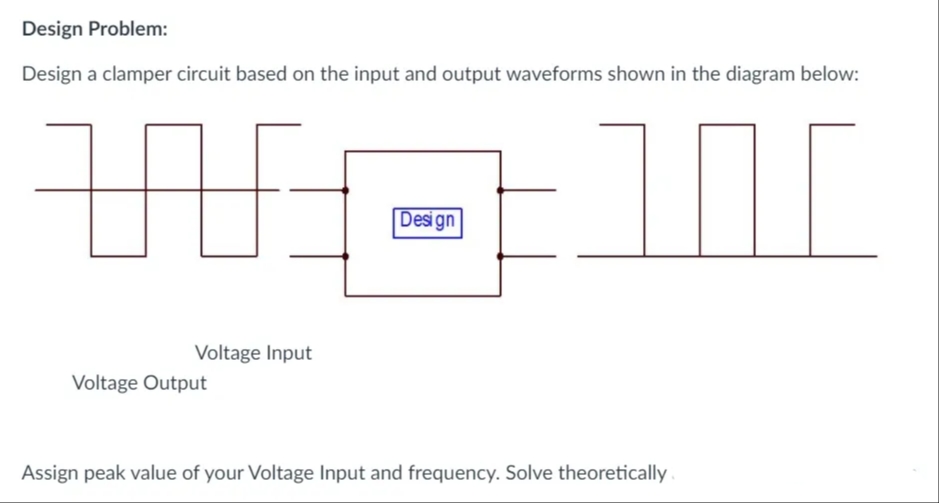
Design Problem: Design a clamper circuit based on the input and output waveforms shown in the diagram below: Design Voltage Input Voltage Output Assign peak value of your Voltage Input and frequency. Solve theoretically.
Design Problem: Design a clamper circuit based on the input and output waveforms shown in the diagram below: Design Voltage Input Voltage Output Assign peak value of your Voltage Input and frequency. Solve theoretically.

Delmar's Standard Textbook Of Electricity
7th Edition
ISBN:9781337900348
Author:Stephen L. Herman
Publisher:Stephen L. Herman
Chapter18: Resistive-inductive Parallel Circuits
Section: Chapter Questions
Problem 13PP: In an R-L parallel circuit, IT=1.25 amps, R=1.2k, and XL=1k. Find IR

Related questions
Question
Please help me with my laboratory activity. Thanks a lot!
Transcribed Image Text:Design Problem:
Design a clamper circuit based on the input and output waveforms shown in the diagram below:
Design
Voltage Input
Voltage Output
Assign peak value of your Voltage Input and frequency. Solve theoretically
Expert Solution
This question has been solved!
Explore an expertly crafted, step-by-step solution for a thorough understanding of key concepts.

Step by step
Solved in 3 steps with 3 images

Knowledge Booster


Learn more about
Need a deep-dive on the concept behind this application? Look no further. Learn more about this topic, electrical-engineering and related others by exploring similar questions and additional content below.Recommended textbooks for you
Delmar's Standard Textbook Of Electricity
Electrical Engineering
ISBN:
9781337900348
Author:
Stephen L. Herman
Publisher:
Cengage Learning
Delmar's Standard Textbook Of Electricity
Electrical Engineering
ISBN:
9781337900348
Author:
Stephen L. Herman
Publisher:
Cengage Learning