Determine the centroid coordinates (X , ỹ) for the beam section shown in Figure Q6. a) Give your answer relative to the origin (0) in millimetres (mm) and to two decimal places.
Determine the centroid coordinates (X , ỹ) for the beam section shown in Figure Q6. a) Give your answer relative to the origin (0) in millimetres (mm) and to two decimal places.

Mechanics of Materials (MindTap Course List)
9th Edition
ISBN:9781337093347
Author:Barry J. Goodno, James M. Gere
Publisher:Barry J. Goodno, James M. Gere
Chapter10: Statically Indeterminate Beams
Section: Chapter Questions
Problem 10.3.6P: A cantilever beam of a length L and loaded by a uniform load of intensity q has a fixed support at A...

Related questions

Question
6a
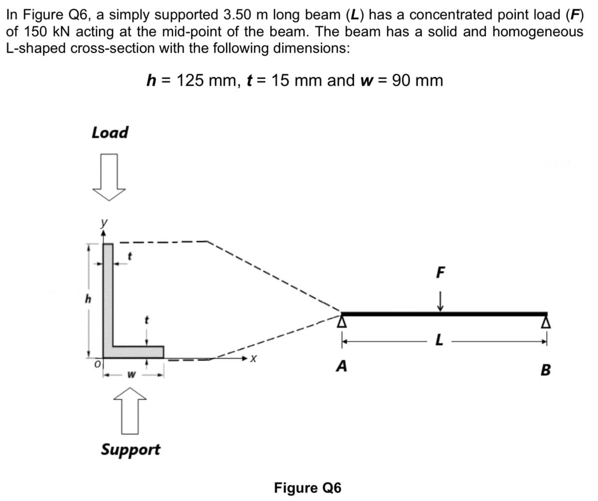
Transcribed Image Text:In Figure Q6, a simply supported 3.50 m long beam (L) has a concentrated point load (F)
of 150 kN acting at the mid-point of the beam. The beam has a solid and homogeneous
L-shaped cross-section with the following dimensions:
h = 125 mm, t = 15 mm and w = 90 mm
%3D
%3D
Load
F
A
B
Support
Figure Q6
Transcribed Image Text:а)
Determine the centroid coordinates (X , ỹ) for the beam section shown in Figure Q6.
Give your answer relative to the origin (0) in millimetres (mm) and to two
decimal places.
Expert Solution
This question has been solved!
Explore an expertly crafted, step-by-step solution for a thorough understanding of key concepts.

Step by step
Solved in 2 steps with 1 images

Knowledge Booster


Learn more about
Need a deep-dive on the concept behind this application? Look no further. Learn more about this topic, mechanical-engineering and related others by exploring similar questions and additional content below.Recommended textbooks for you
Mechanics of Materials (MindTap Course List)
Mechanical Engineering
ISBN:
9781337093347
Author:
Barry J. Goodno, James M. Gere
Publisher:
Cengage Learning
Mechanics of Materials (MindTap Course List)
Mechanical Engineering
ISBN:
9781337093347
Author:
Barry J. Goodno, James M. Gere
Publisher:
Cengage Learning