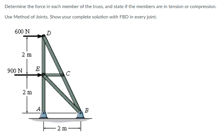
Determine the force in each member of the truss, and state if the members are in tension or compression. Use Method of Joints. Show your complete solution with FBD in every joint.


Q: Description Determine the force in each member of the truss, and state if the members are in tension…
A:
Q: DETERMINE IF THE MEMBER IS UNDER TENSION OR COMPRESSION.
A:
Q: METHOD OF SECTIONS 20 KN 10 KN 10 KN D 3 m. F C G 2 m. 2 m. 2 m. 2 m. DETERMINE MEMBER FORCE RE:
A:
Q: 3. Find all the support reactions A and N and also calculate all the internal forces in the truss…
A: As the questions are independently given as one, as per guidelines I answer the tedious 3rd question…
Q: 3. Determine bar forces GE, GF, EF, ED, FD, and FB. Use the method of joints. D 25 KN 30° B 30 60°…
A:
Q: 15kN 15kN 10 kN 15kN 1.5 m 2.25 m H 1.5 m 2.25 m 1.5 m 1.8 m 18 m 2.4 m. 2.4 m 2.4 m.
A: Given data in question Point loads Span member length To find out Member forces in AJ and AB…
Q: Use the method of joints. Identify the forces in each member of the truss shown in the figure. State…
A: In the method of joint each joint is analyzed using the equilibrium equation and forces in each…
Q: Determine the largest tensile and compressive forces that occur in the members of the bridge truss,…
A:
Q: Use the method of joints to determine the force in each member of the truss shown. State whether the…
A: To find force in each member using method of joint
Q: 300 N D 200 N B 6.0 m E H 3.0 m--3.0 m+-3.0 m-+3.0 m 200 N 400 N
A:
Q: 900 N 300N 1000 N 500N (2m 9m 300N 9m am G 400N 300 N 400 N
A:
Q: Determine using the method of joints the force in each member of the Howe roof truss shown. State…
A: To find force in all members of the truss
Q: Using the method of joints, determine the force in each member of the truss shown. State whether…
A: Draw FBD of:
Q: Problems: 1. Determine the forces acting on members BD, CD and CE of the truss loaded as shown using…
A:
Q: 4.5 m 3.2 m ↓ A B C D 24 kN E
A: Given: P= 24KN To Find: The force in member AC is____ kN. The force in member CE is____ kN. The…
Q: Determine the force in each member of the truss and state if the members are in tension or…
A:
Q: Using the method of joints, determine the force in each member of the truss shown. Summarize the…
A: In the above figure, the force is visible only at joint F = 1000 lb. The magnitude of force at E is…
Q: 2 kN J 1 kN H 0.46 m F D 2.62 m В I A C E G 2.4 m 2.4 m 2.4 m 2.4 m
A: Method of section: The method of sections is a method for calculating the unidentified forces acting…
Q: Calculate the stresses in members AB, BC, and AC then draw FBD. Show complete solutions.
A: To find force in member AB,BC,AC
Q: Find the force in each member of the truss shown. Indicate whether it is in tension (+) or…
A: Finding forces in members of half part because of symmetry of truss and loading
Q: ENGINEERING MECHANICS TRUSS ANALYSIS: 1. SOLVE THE FORCE OF EACH MEMBER USING THE METHODS OF JOINTS…
A:
Q: Please show clear and complete solutions. Box the final answers. Determine the forces in members BE…
A:
Q: Find the member forces required.
A: Analysis of truss can be carried out by: method of joints method of sections. Method of joints is…
Q: D 5 kN 4 m 5 kN E 10 kN 4 m B F 10 kN 4 m G 4 m
A: To find the force in member BC, EF and BE-
Q: F (i) By using the method of joints, determine the force in each 3 member (first, label all the…
A:
Q: Using the method of joints, determine the force in each member of the double-pitch roof truss shown.…
A:
Q: 8 kN 8 kN В L 45° 45° 60° E L D
A:
Q: 1. Determine the forces acting on members BD, CD and CE of the truss loaded as shown using the…
A: Determine the forces acting on members BD, CD and CE of the truss
Q: a- Use the method of joints to determine the force in member EG b- Use the method of sections to…
A:
Q: 2. From the truss shown below, determine the stresses in all members using method of joints and…
A: Given :
Q: Determine (approximately) the force in each truss member of the portal frame. Assume all members of…
A:
Q: Part A Determine the force in member BC of the truss, and state if the member is in tension or…
A:
Q: Using the method of joints, calculate the force in each member of the truss shown. State whether…
A: Introduction- The technique of joints is a method for calculating the unknown forces operating on…
Q: 4. Analyze the truss completely by method of JOINTS. Make a summary of your answers by creating a…
A: Method of joints: The method of joints is one of the methods which is used to solve the unknown…
Q: F G H 4 3 15 ft A E В D y 24 k 30 k 12 k 4 at 20 ft = 80 ft
A:
Q: Using Method of Joints, determine and tabulate all the bar forces. State whether the member is in…
A:
Q: Determine the forces in the members by using the method of section and inspection.
A: Given:- Truss To find:- Forces of members
Q: Solve the truss below and identify if the various members are in Tension and Compression, along with…
A:
Q: 5 kN A B C o D E H Fo |G -a.
A:
Q: 1. Portal Method: The frame shown is subjected to lateral loads as shown. Supports S, T, U V, W and…
A: To Find:- Summarize all the forces in each member
Q: Refer to the given truss, which of the following force members is equal to 11.25k compression? 3 ft…
A:
Q: For this Problem, kindly refer to our Textbook, Structural Analysis Fourth Edition By Aslam…
A: First, we have to draw the required diagram FBD after that we need to apply the equilibrium equation…
Q: 5 kN 2 kN B D E G Using the method of joints, determine all the zero-force members of the Fink roof…
A:
Q: For the steel truss and loading shown, determine the magnitude of the deformation (in inches) of…
A: Given:- Given Data:Cross sectional area = 3.58sq.inX=12fty=7ftP=26131E=29095755 psi.
Q: Determine the force in each member of the truss shown by method of joints. (Summarize and tabulate…
A: To find Forces in all members of the structure.
Q: Determine the forces on each member using method of joints. State also the zero-force members by…
A: Trusses are a structure that is widely used to carry a wide variety of loading conditions under…
Q: ermine the forces in members AB, FG, AH, AG, GH, BI, and CI. State whether the forces are in tension…
A: Draw free body diagram Consider section as shown Consider upper side of the section as shown
Q: I. Determine the force in each member of the truss shown by the method of joints.
A: Draw the free-body diagram of the truss as shown below:


Trending now
This is a popular solution!

Step by step
Solved in 3 steps with 4 images

- A 15" x 3/8" bar of A572 Gr. 50 steel is used as a tension member. It is connected to a gusset plate with 7/8-in diameter bolts as shown in the figure. Use s = 2.0 and g = 3.0. a) Determine the allowable tensile strength of the section based on tensile rupture of the net area.b) Determine the allowable tensile strength of the section based on yielding of the gross area.The angle L 8 x 8 x ½ in tension shown in the figure below must resist aservice dead load of 35 kips, live load of 50 kips, and a roof live load of 2kips. The steel used is A50 (Fy = 50 ksi, Fu = 65 ksi) and its welding length is 4”.Determine if the member has sufficient fracture and yield strength.A 15" x 3/8" bar of A572 Gr. 50 steel is used as a tension member. It is connected to a gusset plate with 7/8-in diameter bolts as shown in the figure. Use s = 2.0 and g = 3.0. Determine the allowable tensile strength of the section based on tensile rupture of the net area.
- TENSION MEMBERS: THE SINGLE 200 X 10 mm STEEL PLATE IS CONNECTED TO A 12 mm THICK STEEL PLATE BY FOUR 16 mm DIAMETER RIVETS AS SHOWN IN THE FIGURE. THE RIVETS USED ARE A502 GRADE 2, HOT DRIVEN RIVETS. THE STEEL IS ASTM A36 WITH Fy = 248 MPa AND Fu = 400 MPa. DETERMINE THE VALUE OF P. a. P BASED ON TENSION OF GROSS AREA b. P BASED ON TENSION OF NET AREA c. P BASED ON BEARING OF PROJECTED AREA d. P BASED ON SHEAR RUPTURE (BLOCK SHEAR)A 15" x 3/8" bar of A572 Gr. 50 steel is used as a tension member. It is connected to a gusset plate with 7/8-in diameter bolts as shown in the figure. Use s = 2.0 and g = 3.0. Determine the design tensile strength of the section based on tensile rupture of the net area. Determine the allowable tensile strength of the section based on yielding of the gross area.Determine whether the compression members shown in the figure is adequate to support the given service loads. a. Use LRFD. b. Use ASD.
- Read the question carefully. Give me right solution according to the question. Find the load P in KN will make the simply supported beam yield due to bending stress if the yield stress is 250 Mpa. vertical load p is acting at mid-span. beam is made of steel E steel =200000 Mpa Ix=372*10^6 mm4 Y centroid=230 mmNote: Hi, pls need help. Any solutions are highly appreciated. I will rate this right away. Thank you in advance! What is the required diameter of sag rods in mm? Considering sag rods and tie rods at midspan (rounded value) A 20m Fink Truss are spaced at 'S' meters o.c. the purlins are made up of C10X20 sections and are spaced 1.1967m on centers. The truss has a height of 4m. Roof LL is 'RLL' N/m2 of roof surface and roof covering is assumed to be 'RDL' N/m2 of roof surface. Determine whether the purlins are adequate to carry such loadings. Given: Fy=248 MPa w=29.76 Kg/m A=3787.09 mm^2 Ix=32.84×10^6 mm^4 Iy=1.17×10^6 mm4 Zx=317.91×10^3 mm3 Sx=258.92×10^3 mm3 Zy=44.25×10^3 mm3 Sy=21.47×10^3 mm3 S= 6 m RLL=900 N/m^2 RDL= 900 N/m^2The strain in the member AB was measured to be 8.9 x 10^-4. If a member is an L3 x 2½ x ¼ of A36 steel, determine the following. a) what is the change in length in inches b) what is the force in the member?
- A bike brake consists of two pieces AOB and COD (Fig.P3.17). Draw the associated FBD for structural element AOB.determine: (a) the elastic section modulus and the yield moment. (b) the plastic section modulus and the plastic moment Mp. Bending is about the x-axis, and the steel is A572 Grade 50. Fy = 345 MPa Subject: Civil Engineering Steel DesignThree plates are welded together to form the curved beam shown. For the given loading, determine the distance e between the neutral axis and the centroid of the cross section. Take l = 4.6 in. The distance e between the neutral axis and the centroid of the cross section is in.