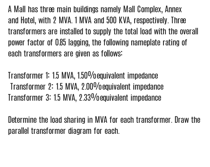
Determine the load sharing in MVA for each transformer. Draw the parallel transformer diagram for each.


Q: Explain the open circuit test on single phase transformer.
A: Open circuit test :- It is carried out at rated frequency & rated voltage to determine the core…
Q: - Why polarity checking is necessary for the parallel operation of single phase transformer.
A: Hello. Since you have posted multiple questions and not specified which question to solve. We will…
Q: The full load voltage drop in a single phase transformer are 2% and 4% due respectively to…
A: Given values are - Voltage dropR%=2%%R=2%Voltage dropX%=4%%X=4%
Q: Q3) What are the elements finding from no-load test of single phase transformer?
A: At no load test rated voltage is applied with secondary open circuited. At no load only magnetizing…
Q: (B) / Draw the simplified equivalent circuit of single phase transformer referred to primary an…
A: In this question , we have to find simplified equivalent circuit of single phase transformer…
Q: 1_ For an unbalanced load connected to a yy transformer, what would be the form/ shape of the output…
A: According to the question we have to discuss about, For an unbalanced load connected to a yy…
Q: A single phase transformer with the maximum value of flux 0.0991wb and an effective cross sectional…
A:
Q: a) With the aid of a well-labeled diagram, describe a step by step approach of conducting a…
A: A continuity test provides the information about a break in either of the coil wires. To perform…
Q: The shell type transformer has less leakage flux compared to the core type transformer True False
A: Choose the correct option Is it true or false? "The shell type transformer has less leakage flux…
Q: what are the advantages and disadvantages of single phase dry-type power transformer when used with…
A: Single-phase dry-type power transformer: Dry-type transformer never uses insulating liquid (which is…
Q: What is instrument transformer? Also discuss the types of instrument transformer?
A: Instrument transformer For a measurement of AC electrical quantities of the system transformers are…
Q: The shell type transformer has less leakage flux compared to the core type transformer True False
A: In the question, choose the correct option? "The shell type transformer has less leakage flux…
Q: For open circuit test which side of the transformer is open circuited?
A: We get same values of parameters irrespective of which side is open circuited.
Q: Derive physically the reason of the phase shift in three phase transformer and show the phase shift…
A: The given problem can be laid down into parts. Firstly, the reason of the phase shift in the three…
Q: With the neat diagram explain the construction and working of Sumpner’s or Back –to-Back test of…
A: Step-1 Construction The Sumpner’s or back-to-back test of a single phase of a transformer…
Q: What is the advantages and disadvantages fot testing transformer?
A: Electrical machines can be either generator or motors. They can be either Ac machines or DC…
Q: In No-Load test circuit of single-phase transformer input power is equal to? In short circuit test…
A: In this question, We need to define the input power in case of open circuit test and short circuit…
Q: single-phase transformer has a voltage regulation of 10% when delivering full load at unity power…
A:
Q: what is the Formulae of short test of single phase transformer and Formulae to determine efficiency…
A: If, Wsc = Full load copper losses Isc = short circuit current Vsc = short circuit voltage Equivalent…
Q: Detailed description of open circuit test on single phase transformer
A: In this question we discuss about open circuit test of transformer .
Q: When rated voltage at rated frequency is applied to a single phase transformer the hysteresis and…
A:
Q: A certain single-phase transformer with full-load copper loss and core loss is loaded at full load.…
A:
Q: 4. What do you mean by transformer connection Ydl and Dy11?
A:
Q: Draw the phasor diagram for no-load practical transformer and mention all parameters in the phasor…
A: Given Draw no load transformers with all the parameter.
Q: )A. Draw approximate transformer model into all quantities of a secondary referred to primary.…
A: Transformer model Equivalent transformer circuit diagram:- Secondary referred to primary side
Q: Differentiate Step-down Transformer and Step-up Transformer
A: The transformer is a device that transfers electric energy from one circuit to another. Based on the…
Q: (i) Illustrate the assumption of an ideal transformer before formulatioi (ii) Formulate Voltage…
A:
Q: xplain the losses of transformer due to
A: The transformer experiences a variety of losses, including dielectric loss, hysteresis loss, eddy…
Q: The per-unit system calculations method eliminates the need for explicit voltage-level conversions…
A: in the per-unit system each voltage is represented in terms of its base value
Q: A lø transformer has an equivalent leakage reactance of 0.04 per unit. The full-load copper loss is…
A:
Q: What are the objectives of implementing an open circuit test on single phase transformer
A: In this question we will write objective of open circuit test on single phase transformers...
Q: 5-Questions : 1- What are the advantages of Transformer Tests?
A: We’ll answer the first question since the exact one wasn’t specified. Please submit a new question…
Q: For short circuit test on 400v/1200v transformer which voltage side will be shorted?
A: The explanation is as follows.
Q: at happens if one phase of a 3-phase transformer fails?
A: Primary delta connected and secondary star connected: If the primary (delta) side loses one phase of…
Q: Explain the difference between transformer equivalent circuit and IM equivalent circuit.
A: Equivalent circuit- An equivalent circuit is a simplified circuit (or model) that is easier to…
Q: TRUE or FALSE: If a transformer is loaded from full-load value to half-load value, then the amount…
A:
Q: What is the definition of zero sequence impedance in transformer? What is the benefit of zero…
A: Transformer: A device which transfer a electrical energy from one circuit to another circuit…
Q: What conclusions we come up with after doing open circuit test on single phase transformer
A: For open circuit test of transformer excite any one winding of transformer at rated voltage and…
Q: Draw the equivalent circuit for a single-phase transformer with all the components referred to the…
A: Equivalent circuit of transformer refer to primary
Q: Q3) What are the elements finding from no-loac test of single phase transformer? Q4) Why Transformer…
A:
Q: A) Name two types of Transformer equivalent circuit and then compare them.
A: We are authorized to answer one question at a time so answering only 1 please upload other question…
Q: What is the Influence of the manner the core coil assembly of the transformer on calculations of…
A:
Q: What are the objectives of conducting an open circuit test on single phase transformer?
A: In transformer its important to judge its performance parameters such as efficiency, regulation etc.…
Q: Write in Briefly about circuit breaker, current transformer and voltage transformer
A: The explanation is as follows.
Q: Draw a complete circuit diagram describing a transformer
A: Electrical machines can be either generator, transformers or motors. They can be either Ac machines…
Q: Define all the losses in the transformer with the diagram and then define the hysterisis loss with…
A: When the transformer is woking on the no-load condition, there are two components of the losses.…
Q: 2- Why the transformer core made from lamination plates?
A: We are authorized to answer the first question since the exact one wasn’t specified. Please submit a…
Q: Calculate the iron loss and copper losses of each transformer for full load condition in back to…
A:
Q: When rated voltage at rated frequency is applied to a single phase transformer, the hysteresis loss…
A:

Step by step
Solved in 3 steps with 3 images

- Consider a single-phase electric system shown in Figure 3.33. Transformers are rated as follows: XY15MVA,13.8/138kV, leakage reactance 10 YZ15MVA,138/69kV, leakage reactance 8 With the base in circuit Y chosen as 15MVA,138kV determine the per-unit impedance of the 500 resistive load in circuit Z, referred to circuits Z, Y, and X. Neglecting magnetizing currents, transformer resistances, and line impedances, draw the impedance diagram in per unit.Three single-phase transformers, each rated 10MVA,66.4/12.5kV,60Hz, with an equivalent series reactance of 0.1 per unit divided equally between primary and secondary, are connected in a three-phase bank. The high-voltage windings are V-connected and their terminals are directly connected to a 115-kV three-phase bus. The secondary terminals are all shorted together. Find the currents entering the high-voltage terminals and leaving the low-voltage terminals if the low-voltage windings are (a) Y-connected and (b) - connected.An infinite bus, which is a constant voltage source, is connected to the primary of the three-winding transformer of Problem 3.53. A 7.5-MVA,13.2-kV synchronous motor with a sub transient reactance of 0.2 per unit is connected to the transformer secondary. A5-MW,2.3-kV three-phase resistive load is connected to the tertiary Choosing a base of 66 kV and 15 MVA in the primary, draw the impedance diagram of the system showing per-unit impedances. Neglect transformer exciting current, phase shifts, and all resistances except the resistive load.
- Consider the single-Line diagram of a power system shown in Figure 3.42 with equipment ratings given: Generator G1: 50MVA,13.2kV,x=0.15p.u. Generator G2: 20MVA,13.8kV,x=0.15p.u. Three-phase -Y transformer T1: 80MVA,13.2/165YkV,X=0.1p.u. Three-phase Y- transformer T2: 40MVA,165Y/13.8kV,X=0.1p.u. Load: 40MVA,0.8PFlagging,operatingat150kV Choose a base of 100 MVA for the system and 132-kV base in the transmission-line circuit. Let the load be modeled as a parallel combination of resistance and inductance. Neglect transformer phase shifts. Draw a per-phase equivalent circuit of the system showing all impedances in per unit.For large power transformers rated more than 500 kVA, the winding resistances, which are small compared with the leakage reactances, can often be neglected. (a) True (b) FalseIn developing per-unit equivalent circuits for three-phase transformers. under balanced three-phase operation. (i) A common Sbase is selected for both the H and X terminals. (ii) The ratio of the voltage bases Vbase/VbaseX is selected to be equal to the ratio of the rated line-to-line voltages VratedHLL/VratedXLL. (a) Only one of the above is true. (b) Neither is true. (C) Both statements are true.
- Consider the single-line diagram of the power system shown in Figure 3.38. Equipment ratings are Generator 1: 1000MVA,18kV,X=0.2perunit Generator 2: 1000MVA,18kV,X=0.2p.u. Synchronous motor 3: 1500MVA,20kV,X=0.2p.u. Three-phase -Y transformers T1,T2,T3,T4,: 1000MVA,500kV,Y/20kV,X=0.1p.u. Three-phase YY transformer T5: 1500MVA,500kV,Y/20kVY,X=0.1p.u. Neglecting resistance, transformer phase shift, and magnetizing reactance, draw the equivalent reactance diagram. Use a base of 100 MA and 500 kV for the 50-ohm line. Determine the per-unit reactances.Figure 3.39 shows a oneline diagram of a system in which the three-phase generator is rated 300 MVA, 20 kV with a subtransient reactance of 0.2 per unit and with its neutral grounded through a 0.4- reactor. The transmission line is 64km long with a cries reactance of 0.5-/km. The three-phase transformer T1 is rated 350MVA.230/20kV with a leakage reactance of 0.1 per unit. Transformer T2 is composed of three single-phase transformers, each rated 100 MVA, 127/13.2kV with a leakage reactance of 0.1 per unit. Two 13.2kV motors M1 and M2 with a subtransient reactance of 0.2 per unit for each motor represent the load. M1 has a rated input of 200 MVA with its neutral grounded through a 0.4- current-limiting reactor, M2 has a rated input of 100 MVA with its neutral not connected to ground. Neglect phase shifts associated with the transformers. Choose the generator rating as base in the generator circuit and draw the positive-sequence reactance diagram showing all reactances in per unit.The ratings of a three-phase three-winding transformer are Primary(1): Y connected 66kV,15MVA Secondary (2): Y connected, 13.2kV,10MVA Tertiary (3): A connected, 2.3kV,5MVA Neglecting winding resistances and exciting current, the per-unit leakage reactances are X12=0.08 on a 15-MVA,66-kV base X13=0.10 on a 15-MVA,66-kV base X23=0.09 on a 10-MVA,13.2-kV base (a) Determine the per-unit reactances X1,X2,X3 of the equivalent circuit on a 15-MVA,66-kV base at the primary terminals. (b) Purely resistive loads of 7.5 MW at 13.2 kV and 5 MW at 2.3kV are connected to the secondary and tertiary sides of the transformer, respectively. Draw the per- unit impedance diagram, showing the per-unit impedances on a 15-MVA,66-kV base at the primary terminals.
- PowerWorid Simulator case Problem 3_60 duplicates Example 3.13 except that a resistance term of 0.06 per unit has been added to the transformer and 0.05 per unit to the transmission line. Since the system is no longer lossless, a field showing the real power losses has also been added to the oneline. With the LTC tap fixed at 1.05, plot the real power losses as the phase shift angle is varied from 10 to +10 degrees. What value of phase shift minimizes the system losses?A single-phase 100-kVA,2400/240-volt,60-Hz distribution transformer is used as a step-down transformer. The load, which is connected to the 240-volt secondary winding, absorbs 60 kVA at 0.8 power factor lagging and is at 230 volts. Assuming an ideal transformer, calculate the following: (a) primary voltage, (b) load impedance, (c) load impedance referred to the primary, and (d) the real and reactive power supplied to the primary winding.With generator conyention, where the current leaves the positive terminal of the circuit element, if P is positive then positive real power is delivered. (a) False (b) True