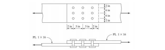
Determine the LRFD design tensile strength and the ASD allowable tensile strength for the member shown, assuming a bearing-type connection. A. A325 16mm bolts, threads are excluded from shear plane b. A325 22mm bolts, threads are excluded from shear plane c. A490 22mm bolts, threads are not excluded from shear plane d. A490 16 mm bolts, threads are not excluded from shear plane 2. Determine the LRFD design tensile strength and the ASD allowable tensile strength Please note: NSCP 2015 Specifications Standard-sized holes Fy = 36 ksi and Fu = 58 ksi unless otherwise noted Deformation at service loads is a design consideration. Do not consider block shear, unless specifically requested For bolts, consider the equivalent diameters in SI (check the table for nominal dimensions


Determine the LRFD design tensile strength and the ASD allowable tensile strength for the member shown, assuming a bearing-type connection.
A. A325 16mm bolts, threads are excluded from shear plane
b. A325 22mm bolts, threads are excluded from shear plane
c. A490 22mm bolts, threads are not excluded from shear plane
d. A490 16 mm bolts, threads are not excluded from shear plane
2. Determine the LRFD design tensile strength and the ASD allowable tensile strength
Please note:
NSCP 2015 Specifications
Standard-sized holes
Fy = 36 ksi and Fu = 58 ksi unless otherwise noted
Deformation at service loads is a design consideration.
Do not consider block shear, unless specifically requested
For bolts, consider the equivalent diameters in SI (check the table for nominal dimensions

Step by step
Solved in 7 steps


