Discussion of Results: 1. Write the measured parameters in Table 1 for Figure 1. Table 1. Measured parameters Resistor No. Resistance Voltage Ampere Watt (acquind irng the omter/ miti-tster) (axguind uirg the voltrster / milti- tester) (acpind using the ater/ miti- tester) facquind ing the watmter 1. I ka 2 10 k2 3. 6.8 ka 4 33 kf2

Delmar's Standard Textbook Of Electricity
7th Edition
ISBN:9781337900348
Author:Stephen L. Herman
Publisher:Stephen L. Herman
Chapter28: Three-phase Transformers
Section: Chapter Questions
Problem 2PA
icon
Related questions
icon
Concept explainers
Question
leplace heiWilrequivale fesisiois. THIS step
and help transform a complex comtinational nesistive circuit into a single equivalert resistance
Iemenbering that series circuits are voltage dividers and paralled circuits are curent dividers.
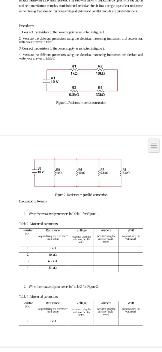
Procecdures:
1. Comect the resistors to the power supply as reflected in figure 1.
2. Measure the different parameters using the electrical measuring instrmert and devices and
write your answerin table 1.
3. Connect the resistors to the power supply as reflectedin figure 2.
4. Measure the different parameters usirg the electrical measuring instrument and devices and
write your answer in table 2.
R1
R2
1kQ
10kQ
V1
-10 V
R3
R4
6.8kQ
33kQ
Figure 1. Resistors in series connection
V2
=10 V
R5
31ko
R6
210kO
R7
26.8kQ
R8
33kO
Figure 2. Resistors in parallel connection
Discussion of Results:
1. Write the measured parameters in Table 1 for Figure 1.
Table 1. Measured parameters
Resistor
No.
Resistance
Voltage
Ampere
Watt
(acquied uing the olmster/
miti-ester)
(acquind uirg the
voltrmeter / multi-
tester)
(acquind using the
amter/ miti-
facquired using the
wattmeter)
tester)
1
I ka
2
10 k2
3
6.8 kn
4
33 k2
2. Write the measured parameters in Table 2 for Figure 2.
Table 1. Measured parameters
Resistor
No.
Resistance
Voltage
Amрere
Watt
(acquired using the ometer/
miti-kster)
(acquied irg the
voltmeter / multi-
tester)
(axpined using the
anmter/ miti-
tester)
facquired uning the
wittmeter)
1
1 ka
Transcribed Image Text:leplace heiWilrequivale fesisiois. THIS step and help transform a complex comtinational nesistive circuit into a single equivalert resistance Iemenbering that series circuits are voltage dividers and paralled circuits are curent dividers. Procecdures: 1. Comect the resistors to the power supply as reflected in figure 1. 2. Measure the different parameters using the electrical measuring instrmert and devices and write your answerin table 1. 3. Connect the resistors to the power supply as reflectedin figure 2. 4. Measure the different parameters usirg the electrical measuring instrument and devices and write your answer in table 2. R1 R2 1kQ 10kQ V1 -10 V R3 R4 6.8kQ 33kQ Figure 1. Resistors in series connection V2 =10 V R5 31ko R6 210kO R7 26.8kQ R8 33kO Figure 2. Resistors in parallel connection Discussion of Results: 1. Write the measured parameters in Table 1 for Figure 1. Table 1. Measured parameters Resistor No. Resistance Voltage Ampere Watt (acquied uing the olmster/ miti-ester) (acquind uirg the voltrmeter / multi- tester) (acquind using the amter/ miti- facquired using the wattmeter) tester) 1 I ka 2 10 k2 3 6.8 kn 4 33 k2 2. Write the measured parameters in Table 2 for Figure 2. Table 1. Measured parameters Resistor No. Resistance Voltage Amрere Watt (acquired using the ometer/ miti-kster) (acquied irg the voltmeter / multi- tester) (axpined using the anmter/ miti- tester) facquired uning the wittmeter) 1 1 ka
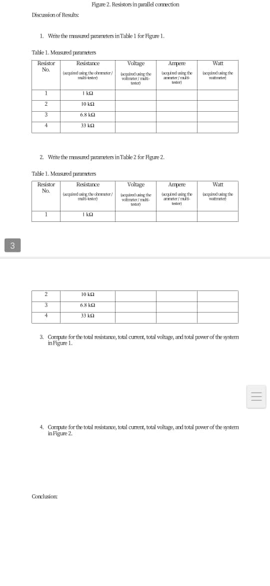
Figure 2. Resistors in parallel connection
Discussion of Results:
1. Write the measured parameters in Table 1 for Figure 1.
Table 1. Measured parameters
Resistor
No.
Valtage
Ampere
Resistance
Watt
(acquind uing the olmmter/
miti-kster)
(acquind uing the
voltmater / multi-
tester)
(acquind using the
ater/ miti-
tester)
facquired using the
wattmeter)
1
1 ka
2
10 kf2
3
6.8 ka
4
33 k2
2. Write the measuId parameters in Table 2 for Figure 2.
Table 1. Measured parameters
Resistor
No.
Resistance
Valtage
Ampere
Watt
(acquined Lsing the okmater/
miti-kster)
(acquireed sirg the
voltmeter/ multi-
tester
(acpind using the
amter/miti-
tester)
faxquied unirg the
wattmeter)
1
I kQ
3
2
10 k2
3
6.8 ka
4
33 k2
3. Compute for the total resistance, total curent, total voltage, and total power of the system
in Figure 1.
4. Compute for the total resistance, total curent, total voltage, and total power of the system
in Figure 2.
Conclusion:
Transcribed Image Text:Figure 2. Resistors in parallel connection Discussion of Results: 1. Write the measured parameters in Table 1 for Figure 1. Table 1. Measured parameters Resistor No. Valtage Ampere Resistance Watt (acquind uing the olmmter/ miti-kster) (acquind uing the voltmater / multi- tester) (acquind using the ater/ miti- tester) facquired using the wattmeter) 1 1 ka 2 10 kf2 3 6.8 ka 4 33 k2 2. Write the measuId parameters in Table 2 for Figure 2. Table 1. Measured parameters Resistor No. Resistance Valtage Ampere Watt (acquined Lsing the okmater/ miti-kster) (acquireed sirg the voltmeter/ multi- tester (acpind using the amter/miti- tester) faxquied unirg the wattmeter) 1 I kQ 3 2 10 k2 3 6.8 ka 4 33 k2 3. Compute for the total resistance, total curent, total voltage, and total power of the system in Figure 1. 4. Compute for the total resistance, total curent, total voltage, and total power of the system in Figure 2. Conclusion:
Expert Solution
steps

Step by step

Solved in 2 steps with 1 images

Blurred answer
Knowledge Booster
Power MOSFET
Learn more about
Need a deep-dive on the concept behind this application? Look no further. Learn more about this topic, electrical-engineering and related others by exploring similar questions and additional content below.
Similar questions
  • SEE MORE QUESTIONS
Recommended textbooks for you
Delmar's Standard Textbook Of Electricity
Electrical Engineering
ISBN:
9781337900348
Author:
Stephen L. Herman
Publisher:
Cengage Learning
Power System Analysis and Design (MindTap Course …
Electrical Engineering
ISBN:
9781305632134
Author:
J. Duncan Glover, Thomas Overbye, Mulukutla S. Sarma
Publisher:
Cengage Learning
EBK ELECTRICAL WIRING RESIDENTIAL
Electrical Engineering
ISBN:
9781337516549
Author:
Simmons
Publisher:
CENGAGE LEARNING - CONSIGNMENT
Electricity for Refrigeration, Heating, and Air C…
Mechanical Engineering
ISBN:
9781337399128
Author:
Russell E. Smith
Publisher:
Cengage Learning