Do the following: (a) Drive the truth table for a circuit which will control LED segment "c" of a seven-segment display. For example, for number 0, 1, 3, your LED representing "c" should light up, whereas for numbers such as 2, E, or F it should not. (b) Use Karnaugh map reduction to get a simplified Boolean function design for a seven-segment decoder that uses a minimum number of gates in sum-of-product form. (c) Implement your circuit in the simulator, using only NAND and NOT gates.
Do the following: (a) Drive the truth table for a circuit which will control LED segment "c" of a seven-segment display. For example, for number 0, 1, 3, your LED representing "c" should light up, whereas for numbers such as 2, E, or F it should not. (b) Use Karnaugh map reduction to get a simplified Boolean function design for a seven-segment decoder that uses a minimum number of gates in sum-of-product form. (c) Implement your circuit in the simulator, using only NAND and NOT gates.

Chapter22: Sequence Control
Section: Chapter Questions
Problem 6SQ: Draw a symbol for a solid-state logic element AND.

Related questions
Question
I will give thumbs up
Transcribed Image Text:CP213 - Winter 2021 Lab 4: Combinational Logic
082895637
89860888
ast Minute
ENGINFER
ENGINEERS
89880888
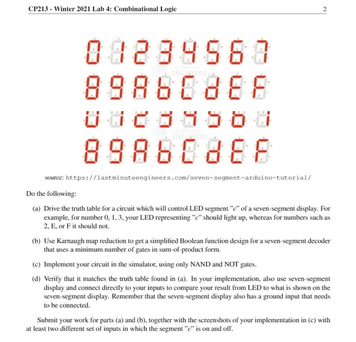
source: https://lastminuteengineers.com/seven-segment-arduino-tutorial/
Do the following:
(a) Drive the truth table for a circuit which will control LED segment "c" of a seven-segment display. For
example, for number 0, 1, 3, your LED representing "c" should light up, whereas for numbers such as
2, E, or F it should not.
(b) Use Karnaugh map reduction to get a simplified Boolean function design for a seven-segment decoder
that uses a minimum number of gates in sum-of-product form.
(c) Implement your circuit in the simulator, using only NAND and NOT gates.
(d) Verify that it matches the truth table found in (a). In your implementation, also use seven-segment
display and connect directly to your inputs to compare your result from LED to what is shown on the
seven-segment display. Remember that the seven-segment display also has a ground input that needs
to be connected.
Submit your work for parts (a) and (b), together with the screenshots of your implementation in (c) with
at least two different set of inputs in which the segment "c" is on and off.
Expert Solution
This question has been solved!
Explore an expertly crafted, step-by-step solution for a thorough understanding of key concepts.

This is a popular solution!

Trending now
This is a popular solution!

Step by step
Solved in 4 steps with 2 images

Knowledge Booster


Learn more about
Need a deep-dive on the concept behind this application? Look no further. Learn more about this topic, electrical-engineering and related others by exploring similar questions and additional content below.Recommended textbooks for you