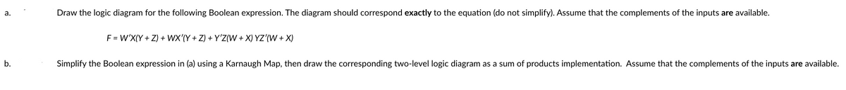
Draw the logic diagram for the following Boolean expression. The diagram should correspond exactly to the equation (do not simplify). Assume that the complements of the inputs are available. F = W'X(Y+Z) + WX'(Y+Z) +Y'Z(W+X) YZ'(W+X) Simplify the Boolean expression in (a) using a Karnaugh Map, then draw the corresponding two-level logic diagram as a sum of products implementation. Assume that the complements of the inputs are available.
Q: For the following circuits, solve for the values as indicated. Round your answers to the nearest…
A: here we have to find the Total Resistance.
Q: Q2 Determine the current Iy in figure shown by using Nodal analysis method. 20 30 w 40 10 SA 20
A:
Q: At inversion, the surface pf an NMOS transistor is ??
A:
Q: Here is the general instruction for your SA3 Submission. Generate the Truth table of the input and…
A: According to the question, For BCD to 5421 code and BCD to 2421 code, we need to find Generate the…
Q: 2 Sketch the root locus plot for R(s) + 3 (s+3)(s²+3s+3) K Y(s)
A: In this question we need to draw the root locus of the given system.
Q: Determine the phase difference between the two waves v1 (t)=10 sin( 377t-30)V v_2 (t)=10 sin(…
A: Given data, Voltages are given, v1t=10sin377t-300 V.v2t=10sin377t+900 V.
Q: 2. for the following circuit find the value of the current I. 100 200
A:
Q: Imaginary Axis -2 -3 A unity feedback system with G (8) -2.5 -2 -1.5 Nyquist Diagram -0.5 Real Axis…
A: Given data Forward path gain; Gs=-s2+5s+6s2-3s+2 Feedback gain; Hs=1 The Nyquist plot is also given…
Q: For the circuit shown below, find and io, vo and i for all time, assuming that the switch was open…
A:
Q: An LED is very efficient because within the LED itself, the electrical energy is directly converted…
A: As per Bartleby's guidelines, Only 3 subparts can be solved. Please send other subparts separately.…
Q: How could I get the thevnin voltage from this using the transfer funciton and the lookback method?
A: Given: Required: How to get Thevenin's voltage by using the transfer function and the lookback…
Q: Consider a generator that rotates its 200 turn, 0.18 m diameter coil at 3500 rpm in a 0.95 T field.…
A: We need to find out peak voltage for given generator .
Q: What is FR4?
A: Answer: to find about FR-4
Q: A battery with & = 7.00 V and no internal resistance supplies current to the circuit shown in the…
A: The required resistor value can be calculated by applying kirchhoff's voltage law to the circuit at…
Q: 8. A medium single phase transmission line 100km long has resistance/km 0.250, reactance/km 0.802,…
A: 8. Given Data: A medium transmission line with, Total Resistance R=0.25×100 ? Total reactance…
Q: 2) Draw a phasor diagram showing the supply voltage, the voltage across R, the voltage across L and…
A: In this question We need to draw the phasor diagram. We know Current in the impedance Z, I= V/Z
Q: F(J, K,L,M) = = IIM (0,1,4,5,8,10,12,14), find the simplified POS.
A: We need to find out simplified form of given Max term function .
Q: V₂ Assuming the diodes to be ideal wis the figure for the output to be clipped, the impot volley Vp…
A: We need to find out the range of input voltage to get clipped output .
Q: a) The input and impulse response of an LTI system is depicted in Figure 3.a. Solve and sketch the…
A: it is asked to solve and sketch the output of the system for given input and impulse response
Q: 1. Find the maximum real power that can be transferred to an impedance ZL connected between…
A: Given circuit: To determine: The maximum real power that can be transferred to ZL
Q: For the cct shown below find zt and drow the equivalent cct lpp 4H Cgdp RE www Cgdn CPD VDD Mp Mn…
A:
Q: In residential and commercial buildings, what kind of circuit connection is being used? Is it series…
A: Type of connection which is used in residential and commercial buildings : Parallel connection…
Q: The switch in the circuit has been in position a for a long time. At t=0 the switch is moved to…
A:
Q: Minimize the following function using the Quine-McCluskey method. Provide all required tables.…
A: Given: A boolean function, fA,B,C,D=∑m 0, 2, 4, 5, 7, 9, 11, 12, To do: Minimize the given boolean…
Q: V₁ 12 V ww R1 1 ΚΩ A B ww R2 2 ΚΩ R3 3,3 ΚΩ - V₂ 5 V Figure 3-1: Circuit to test the Superposition,…
A:
Q: Estimate the sensitivity of the closed loop transfer function T with respect to parameter b. (Show…
A: Given, Sensitivity=?
Q: For the circuit shown find the impedance phase angle Z (in degrees) i= 0.02 sin(157t+40) 17 2517…
A: Given data, Circuit diagram is given as,
Q: Find RTH with respect to terminals a and b. b 8Ω iT Figure 2: 3ix 252 m
A: Here the above circuit contains the dependent source so resistor reduction not possible then apply…
Q: Applying transformation of successive sources, obtain the circuit that allows to calculate the…
A:
Q: Why would a radar system designer choose to use L-band instead of X-band? Choose all correct…
A:
Q: Find vo(t) in the circuit below, assuming vo(0) = 5V. 10 92 ww 10e ¹u(t) V (+ 10 Q2 www vo(1) 0.1 F…
A:
Q: ܢ ܒ t Determine ABCD (transmission) parameters of the network shown. كه 1F IF m
A:
Q: Convert the following boolean expressions to their standard expanded form. Show all steps and…
A: In the given questions we need to find the standard expanded form of the given Boolean expression.
Q: Outline the requirements from the design and installation of a battery room. State the battery…
A: To do: Outline the requirements from the design and installation of a battery room. State the…
Q: You have to replace 1500 ohms resistor in radio. You have three of 1000 ohms resistors. How will you…
A: I have written this solution as handwritten solution. Hope you find the perfect solution.
Q: Www Μ 6Ω 5Ω 30 5 V 2 Α Μ 15 Ω 8 V 10 Ω μ 10 V 4 Ω Μ 4Ω Determine the power supplied by each of the…
A:
Q: Assuming the dioder to be ideal is the for the output to be clipped, the impot volta figure Vp must…
A: It is given that:
Q: Describe the operation of a see-through latch and its potential applications.
A: Answer: to describe the operation of see- through latch
Q: Vi(t) I I CCT1 ! R₁ I CCT2 Li ooooo 00000 L2 L₁ 00000 R₂ R Rf OA1 OA2 R ip#, Vp# in#, Vn# Ra Ra CCT3…
A:
Q: 5. Given the following circuit, solve for RTH, VTH, and I. Must use Thevenin's Theorem. 12 V +1 6 ΚΩ…
A:
Q: How many time constants does it take to deliver 89 % of the found energy?
A:
Q: A band-limited signal with a maximum frequency of 5 kHz is to be sampled. According to the sampling…
A: Given: Bandlimited signal with a maximum frequency up to 5kHz is to be sampled.
Q: Determine iz(t) in the circuit shown in Figure P4.50. Assume: i(t) = 100 cos(wt + 4)mA is(t) = 80…
A:
Q: Refer to Figure 2. What is IB? 3.375mA Onone in the given choices O 4.4mA O 1.03125mA
A:
Q: b) A single-phase induction motor, ¼ hp, 120 V, 50 Hz, 3% slip has the following equivalent circuit…
A:
Q: 1. A sinusoidal signal makes 80000 cycles in one minute, what is the period of this signal?
A: 1. Given :- 80000 cycles in 1 minutes Find:- Period of the signal
Q: Find the Fourier transform of f(x). f(w) = f(x) = -9, if -9 < x < 0 9, if 0<x<9 0, otherwise
A:
Q: Given the following circuit, solve for Io. Must use source transformation.
A:
Q: How do you derive the Telegrapher's Equations for a lossy transmission line? Why is it the bottom…
A: According to the question, we need to derive the Telegrapher's Equations for a lossy transmission…
Q: Design an ammeter and voltmeter that work in one switch, the current is one milliamp, the internal…
A: In this question We need to design an multimeter for measure the different different voltage. We…
Trending now
This is a popular solution!
Step by step
Solved in 3 steps with 2 images
- Using the analysis technique where you first extract the truth table and then use it to derive the output’s logic expression, analyze the circuit. Record your results below. I added the circuit as an image Conclusion In your own words, describe the process used to analyze a logic circuit where you first extract a truth table and then derive the logic expression. 2.Again, in your own words, describe the process used to analyze a logic circuit where you first extract the logic expression and then derive the truth table.Assume that you are given the task of designing a logic circuit to help determine the best time to plan a garden. There are three possible factors: 1) Time, where 0 represents day and 1 represents evening; 2) Moon, where 0 represents 20 Celsius and below, and 1 represents over 20 Celsius. These three factors represent inputs. After significant experimentation, it was found that the best time to plan a garden is during the evening with a full moon (temperature does not appear to matter. This results in the following truth table. Time (x) Moon (y) Temperature (z) Pant? 0 0 0 0 0 0 1 0 0 1 0 0 0 1 1 0 1 0 0 0 1 0 1 0 1 1 0 1 1 1 1 1 Convert the truth table to a Boolean function F, in its simplified form, and draw a logic gate which equivalent to the function.Topic: Boolean Algebra and Circuit Simplification Instructions. a. Write Boolean expression of the logic circuits shown below. b. Develop a truth table for each output of the circuits. C. Simplify the Boolean expression d. Draw the simplified equivalent circuit.
- For the logic circuit shown: 1. Write the Boolean expression that directly implements this circuit. 2. Simplify the Boolean expression using Boolean identities. Identify the identities used as each step. 3. Simplify the Boolean expression using a Karnaugh map. Show the sum of products form, the truth table, resulting map with the groupings marked, and the simplified expression. 4. Draw the combinational circuit resulting from the simplified circuit.*A traffic light system uses logic gates as part of the control system. The system is operated when the output D has the value . This happens when either (a) signal A is red or (b) signal B is green and signals B and C are both red( NOTE: Assume for this problem that red=0 and green =1) Deduce the truth table for the system and the Boolean expression from the truth table, Hence Design a logic circuit or networkThe function of a programming is given below: F = A'B'C'D + A'B'CD' + A'BC'D + A'BCD' + AB'C'D + AB'CD' + ABC'D + ABCD' (a) Translate a function given above into a truth table with F as the Output.(b) Simplify the F function above.(c) Determine the logic gates required for the function.(d) Draw the logic gates based on the solution in (c).
- B) A coin-operated cold drink dispenser will provide cold drink (D) under the following conditions: The correct coin (C) is inserted AND A paper cup is in position (P) AND The selector is set t Orange (O) OR Sprite (S) OR Lemonade (L) Write the Boolean expression for the output of the dispenser. Represent the operation of the dispenser in logic circuit 4 get a logic circuit to mimic aorporate checquing system for operatore of a compnnyWhich of the following statements accurately represents the best method of logic circuit simplification? a. Actual circuit trial and error evaluation and waveform analysis b. Boolean algebra and actual circuit trial and error evaluation c. Karnaugh mapping and circuit waveform analysis d. Karnaugh mapping and Boolean algebraConsider the Boolean expression: u = wx + yz + wx'z' + w'y. (a) Draw the Karnaugh map for u.(b) Use the map in part (a) to obtain the Karnaugh map for u'.(c) Express u' as a minimal sum of products.(d) Design a simple logic network for u'.
- Draw the logic diagram of the following Boolean expression after simplifying it: A+CD+(A+D’)(C’+D)Given the Boolean expression a’b + a’c’ + abc,a. Convert the expression to the other standard form. What do you call this standard form?b. Derive its canonical form. What do you call this canonical form? c. Derive the other canonical form. What do you call this canonical form?d. Provide the truth table of the expressione. Draw the logic circuit diagrams of the 2 standard forms4.1 Investigate if the following Boolean “identity” is correct, or not. If it is not correct, formulate the correct version of the identity (?′?+?)′=?+?′?′. [2]4.2 Use the identities of Boolean algebra to verify the following identity: [4]?(?+?)+??′+??′+?=?+?+?4.3 Consider the logic gate circuit below:a) Formulate the Boolean expression corresponding to the output of the logic circuit diagram above. [2]b) Hence, show that the Boolean expression formulated in part (a) reduces to ??+?. [3]c) Draw the logic gate circuit diagram corresponding to the reduced expression inpart (b) above. 3.1 Let r, s, t denote the statements “Joe is registered for MCI511S”, “Joe will go to the zoo next week”, “Joe is registered for PBT512S”, respectively. Translate the symbolic statement (∼?∨?)→∼? into words. [2]3.2 Write the negation of the statement “If Joe writes the exam, he will go the airport but he will not catch the flight”. [2]3.3 Determine the truth value of the compound statement (?∧∼?)∨∼?, if p…