Draw the shear force and bending moment diagrams. Determine its required diameter if oallow = 140 MPa and t
Q: |5 kips 30 kip · ft 1= 90 in.. 6 in. |B NA D 4 ft 2 in. 4 ft
A: given; lets take reaction force at point D=Rmoment at point B (MB)=30kip.ftmoment of inertia (I)=90…
Q: The wooden section of the beam is reinforced with two steel plates as shown. If the beam is…
A: Given data as per question Ew = 10 GPa Est = 200 GPa. Free body diagram of the composite section
Q: Draw the shear and bending-moment diagrams for the beam and loading shown, and determine the maximum…
A: Let Ay and Dy be the vertical support reactions at A and D, respectively. Also, at A there will be a…
Q: Q3: The wooden section of the beam is reinforced with two steel plates as shown. If the beam is…
A:
Q: The eye hook has the dimensions shown. If it supports a cable loading of 800 lb, determine the…
A: Draw the free-body diagram of the hook.
Q: m= 28 KN-M P=28 -14樂 AB C=4 d1e=1:
A: given overhanging beam
Q: The steel shaft is subjected to the two loads. If the journal bearings at A and B do not exert an…
A: Data given- Allowable stress = 180 Mpa Load = 4KN at an angle of 30° from y axis
Q: y = 30 kN %3D 4 m 3 m 3 m D = 20 mm E A В D Cp = 40 kN • m
A:
Q: Determine the internal normal force at point C, if F = 48 kN . Determine the shear force at point C…
A:
Q: The bar has a thickness of 1 in. and the allowable bending stress is sallow= 30 ksi. Determine the…
A:
Q: F kip Determine the internal normal force and shear force, and the bending moment in the beam at…
A: From the given data,
Q: If the beam is subjected to a bending moment M = 50 kN-m, determine a.) the maximum bending stress…
A:
Q: 10 kips 40 kips 5kipilpt E B t. 6t. 8Ft t l0pt RA Rp
A:
Q: Determine the internal normal force, shear force, and bending moment at point C in the beam. 10 kN…
A:
Q: The shaft is supported by a thrust bearing at A and journal bearing at D. If the shaft has the cross…
A: Given data: Inner radius, r = 25 mm Outer radius, R = 40 mm Therefore, Inner diameter, d = 50 mm…
Q: 8 FBD carryT Draw the shear force and bending moment diagrams for this beam 300 tb /ft 150 lb/ft -12…
A: Given simply supported beam with uniformally distributed load condition
Q: The beam is subjected to a moment of M = 40 kN # m. Determine the bending stress at points A and B.…
A: Write the expression of the moment of inertia of the cross-section.
Q: If the beam is subjected to a bending moment of M = 50 kN # m, sketch the bending stress…
A: According to the given diagram, the cross-section is triangular and the centroid of a triangle is…
Q: 450 lb/ft Q2/ If the beam has a square cross section of 9 in. on each side, determine the absolute…
A:
Q: Determine the resultant internal normal force, shear force, and bending moment at point C in the…
A: Draw the free-body diagram of the section AB. Draw the free-body diagram of the section BC.
Q: Determine the maximum stress produced by the loads and create the shear and moment diagrams for the…
A: Given data as per the question Diameter =1 in we know thataccording to bending…
Q: The bar has a thickness of 0.5 in. and the allowable bending stress is sallow= 20 ksi. Determine the…
A: The maximum stress in the beam is written as, The ratio r/h and w/h is written as,
Q: 5 kN 60 mm B -150 mm 400 mm
A: A beam is defined as a structural member subjected to transverse shear load during its…
Q: A cantiliver beam subjected to a uniform load along its length and axial load P. Draw the shear…
A:
Q: The shaft is supported by smooth journal bearings at A and B that only exert vertical reactions on…
A: Given data: Diameter of the shaft, d = 90 mm Let, RA = Vertical reaction at A RB = Vertical reaction…
Q: Determine the magnitude of the internal loads(normal, shear, and bending moment) at point C.
A: The given member can be cut into two parts along C and the above part can be drawn as below, Here,…
Q: Determine the resultant internal normal force, shear force, and bending moment at point C in the…
A:
Q: The shaft is supported by a smooth thrust bearing at A and smooth journal bearing at C. If d = 3…
A: The bearings at A and C will be replaced by two vertical reactions because there is vertical load…
Q: If the beam is subjected to a moment of M = 100 kN # m, determine the bending stress at points A, B,…
A: Given: The bending moment, M = 100 kN.m The Centroid of the cross-section,
Q: Determine the internal normal force and shear force, and the bending moment in the beam at points C…
A:
Q: Question 3 Draw the shear force and bending moment diagram for the loaded cantilever beam. And state…
A: givencantilever beam length L=4mP=10kN
Q: Draw the shear and moment diagram and determine the Vmax and Mmax of the cantilever beam shown…
A:
Q: The bar has a thickness of 0.5 in. and is subjected to a moment of 600 lb # ft. Determine the…
A: Given: r=0.3 inh=2 inw=6 int=0.5 inM=600 lb.ft
Q: 5 ENim 4Nim D -2 m 2 m -2 m- -2 m-
A: Shear force diagram represents shear force at every section of the beam. Shear force at any…
Q: Determine the maximum bending stress in the beam’s cross section.
A: The expression for the moment of inertia of the section about x-axis, Iz=bd312 Here, bis the breadth…
Q: Determine the internal forces (axial force, shear force, and bending moment) at point j of the…
A:
Q: Draw the Shear and Moment Diagram and determine the Max. Bending Stress and Max. Web Shear Stress. 5…
A: The free body diagram of the beam is given below, On taking moment about D, Force equilibrium…
Q: 2. If the beam is subjected to a bending moment of M = 50 kN m, sketch the bending stress…
A:
Q: can you solve this?
A: Draw the free-body diagram of the beam.
Q: The beam is made from three boards nailed together as shown. If the moment acting on the cross…
A: Given data: M = 1 kip.ft M = 1000 lbs×12 in = 12000 lb.in Determine the maximum bending stress,…
Q: Write shear and bending moment equations at point B. з KN/m 10 KN B 3 m D 1m
A:
Q: maximum tensile and compressive bending stress in the beam if it is subjected to a moment M = 6…
A: Detailed solution given below.
Q: If the beam in Prob. 6–28 has a rectangular cross section with a width b and a height h, determine…
A: Given Data: The load acting on the beam is 12 kN and 20 kN. The free-body diagram of the beam can…
Q: Determine the resultant internal normal force, shear force, and bending moment at point C in the…
A: The free-body diagram of the beam can be drawn as below, Here, RAH is the horizontal reaction at A,…
Q: Determine the slope at point B. Draw the shear and bending moment diagrams. Assume constant El. W B…
A: Draw the free body diagram of the beam:
Q: FI-6. Determine the resultant internal normal force, shear force, and bending moment at point Cin…
A:
Q: 1. Determine the internal normal force, shear force, and bending moment at point C in the beam. 300…
A:
please answer all parts step by step and clear answer.
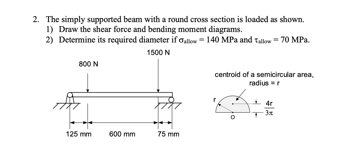
Step by step
Solved in 2 steps with 3 images
- The three beams shown have approximately the same cross-sectional area. Beam 1 is a W 14 X 82 with flange plates; beam 2 consists of a web plate with four angles; and beam 3 is constructed of 2 C shapes with flange plates. Which design has the largest moment capacity? Which has the largest shear capacity? Which is the most economical in bending? Which is the most economical in shear? Assume allowable stress values are: = 18 ksi and ra=11 ksi. The most economical beam is that having the largest capacity-to-weight ratio. Neglect fabrication costs in answering parts (c) and (d) above. Note: Obtain the dimensions and properties of all rolled shapes from tables in Appendix F.1. Determine the maximum positive bending moment in the beam in kN-m. 2. Determine the maximum shear in kN. 3. Determine the location of Neutral Axis, in mm, from the top of the section. 4. Determine the location of the centroid, in mm, from the left of the section. 5. Determine the moment of inertia of the section in x106 mm4 . 6. Determine the moment capacity of the section, kN-m, if fbcap≤300 MPa. 7. Determine the maximum flexural stress experienced by the beam in MPa. 8. Determine the maximum shearing stress in MPa at Neutral Axis. 9. Determine the spacing of rivets in mm. 10. Determine the maximum flexural stress at 1 m from the support at D to E in MPa.A loaded beam, 60 mm wide by 100 mm high and 6 m long, has the shear and moment diagrams as shown below. Determine (a) the magnitude, type and location of the maximum flexural stress (in MPa) (b) the stress (specify the type) in a fiber 30 mm from the top of the beam at a section 3.5 m from the left end. I = bh3/12
- The beam safely supports shear forces and bending moments of 2kN and 6.5 kN-m respectively. Based on this criterion, can it be safely subjected to the loads F = 1kN and C = 1.6 kN-m? Use the area methodDetermine internal shear force, internal bending moment and internal normal force at point cDetermine the ratios of the weights of four beams that have same length.are made of the same material,are subjected to the same lmaximum bending moment,and have the same maximum bending stress if their cross sections are (I) a rectangle with height equal to twice the width,(2) a square,(3) a circle , and (4) a pipe with outer diameter d and wall thickmess f = di% (see figures).
- The structure shown below consists of a brass core inserted into a steel tube of cross section square. If a moment of 8 kN × m is applied at its end, determine the maximum bending stress in the bar. Elaton = 100 GPa, Steel = 200 GPa.An I section symmetrical beamhas 200mm wide flange and overall depth of 500mm. Each flange is 25mm thickand the web is 20mm thick. Determine the maximum bending moment that should be imposed in the sectionif the tensile or the compressive stressis not to exceed 40MN/m^2 and what percentage of the moment is resisted by flange or web?The beam weight is 5kN considered as a distributed load over the beam length. Two bushwalkers with 850N weight each are standing together at one end of the beam/bridge. Determine the maximum shear force and bending moment in the simply supported beam shown below.
- The beam is constructed from four pieces of wood, glued together as shown. If M = 10 kip # ft, determine the maximum bending stress in the beam. Sketch a three-dimensional view of the stress distribution acting over the cross section.Draw the shear stress diagram and bending moment diagram for a beam with the free body diagram shown below. Identify the location of critical point(s) in the beam. Given AB = 0.5 m, BC = 0.6 mm, and CD = 0.5 m.A 10-ft long overhanging beam is loaded as shown. Determine the following: 10 kips 8 kips 5 kips 5 kip-ft K 3 ft -1 ft A B 2 ft . 4 ft C D E 1. Reaction at D (kips) 2. Shear at C (kips) 3. Moment at D (kip-ft) 4. Maximum shear (kips) W 5. Maximum moment (kip-ft)