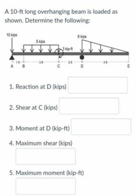
A 10-ft long overhanging beam is loaded as shown. Determine the following: 10 kips 8 kips 5 kips 3 kip-it 38 28 A B D E 1. Reaction at D (kips) 2. Shear at C (kips) 3. Moment at D (kip-ft) 4. Maximum shear (kips) 5. Maximum moment (kip-ft)
Q: Calculate the maximum def lection δmaxof a uniformly loaded simple beam if the spanlength L = 2.0 m,…
A: Given Load, q = 2 kN/m Length, L = 2 m E = 70 GPa Find Maximum deflection
Q: A beam is subjected to equal bending moments of M, = 52 kip-ft. The cross-sectional dimensions are…
A:
Q: Consider the beam shown. Suppose that the distributed load w = 650 lb/ft . Follow the sign…
A:
Q: Draw shear force digam and bending moment digram for the following beam 2.0 kips / ft A В 15.0 ft…
A: Let RA and RB are reactions at A and B By using law of equilibrium RA+RB =12 Moment at point A is…
Q: A beam of rectangular section of 12 cm × 20 cm is simply supported over a span of 12 m. It is acted…
A: Given data: - The width of the beam is b = 12 cm. The height of the beam is d = 20 cm. The load…
Q: . Cantilever beam carrying a distributed load with intensity varying from Wo at the free end to zero…
A:
Q: P pt 200 mm C B. 250 mm 300 mm 550 mm Act Given: Beam AB 75mmx100mm Beam CD 50mmx50mm P- BkN W =…
A:
Q: * For the cantilever beam shown. find the value of compound Shear stress :at point D 4 KN 6 KN.m D.…
A: Answer: (a) The compound shear stress at point D is 31.3217 MPa. (b) The compound shear stress at…
Q: a)A simply supported beam of length 6 m ,carries point load of 3 kN 4 m from the left end. Draw the…
A:
Q: Use a = 21 ft, b = 7 ft, and w = 6 kips/ft. The reaction forces for this beam are A, = 56 kips and…
A: A beam is defined as a structural member subjected to transverse shear load during its…
Q: A beam with a solid homogeneous rectangular section is simply supported at A and B. A concentrated…
A: Given Data: The magnitude of load, F=150 kN
Q: A cantilerver beam AB, 2.5 m long carries a uniformly distributed load of 2 kN/m over a length of 2…
A:
Q: A beam with a solid homogeneous rectangular section is simply supported at A and B. A concentrated…
A:
Q: 14. In a simple supported beam having length = I and subjected to a concentrated load (P) at…
A:
Q: A cantilever beam 2m span carries point loads as shown. Draw the shear force and bending moment…
A:
Q: Example: Draw Shear & Moment diagrams for the following beam 12 kN 8 kN А C В 1 m 3 m 1 m - RA = 7…
A: The free body diagram of the beam is given below,
Q: A beam with a solid homogeneous rectangular section is simply supported at A and B. A concentrated…
A:
Q: Please draw shear force diagram and bending moment diagram for the following beam and also indicate…
A: Draw the free body diagram of the beam.
Q: Using the coordinate axes shown, write equations for the shear V and bending moment M for any…
A: The free body diagram for the beam is given below,
Q: Draw the shear and moment diagram of the cantilever beam shown below. For this part, please show the…
A: Draw a free-body diagram of the given beam. Apply force equilibrium in a horizontal direction.…
Q: A 10-ft long overhanging beam is loaded as shown. Determine the following: 10 kips 8 kips 5 kips 3…
A:
Q: For the beam and loading shown, draw the shear force and bending moment diagrams of the beam AC.…
A: The free-body diagram of the beam is given as, In this diagram, 2 kN load is displaced at point C…
Q: Maximum bending moment: A simply supported rectangular beam that is 3000 mm long supports a point…
A: Write the given data. P=5000 NL=3000 mmb=127 mmh=254 mmd=254 mm
Q: Draw the shear and bending-moment diagrams for a cantilever beam AB of span L supporting a uniformly…
A: Given: Cantilever beam AB with a length of L. The UDL acting on the beam is w. Total load = force…
Q: For the beam shown below, write the shear and moment equations for segment BC. 60 KN 40 KN/m A C…
A:
Q: 180 lb/ft 4 in. LA B 8 in. 12 ft | 1200 1b
A: Given, b = 4 in d = 8 in To find maximum bending stress, we will need to find maximum bending…
Q: 6 kN/m 3 m 3 m B 1 m Figure 1 shown the T- shape beam is exerted with the distributed load. Given…
A:
Q: 5 kN HW23.3 - Find the shear and bending moment diagrams for the compound beam. The reactions at…
A: Before drawing the Shear Force Diagram (SFD) and Bending Moment Diagram (BMD), We need to consider…
Q: A cantilever beam of length 2m is subjected to a vertical downward load of 2kN at the free end. Draw…
A: Given data: Length of cantilever beam = 2 m The magnitude of downward load = 2 kN…
Q: For the same beam as in Question 1, if the applied moment Mz on the cross section is 1.0 kN.m, the…
A:
Q: A beam with a solid homogeneous rectangular section is simply supported at A and B. A concentrated…
A:
Q: Advanced Physics For the beam shown, you must draw, applying the method of sections, the shear and…
A: given; w1=5N/mw2=10N/mP=8NM=20N.mlets take reaction force at A=RA
Q: 4.) A W10X33 steel wide-flange beam has a span of 30 ft., and is loaded and supported as shown.…
A: GivenW10×33 steelZx=section modulus=35in3
Q: A cantilever beam 2m span carries point loads as shown. Draw the shear force and bending moment…
A:
Q: d kN kN/m The beam shown above has been supported at points A. Magnitude Your Student ID's last two…
A:
Q: Determine the maximum bending moment for the beam shown below. Use a = 8 ft, b = 12 ft, c = 6 ft,…
A:
Q: Draw the shear and moment diagram of the cantilever beam shown below. For this part, please show the…
A: Consider upward force & CW moment as (+)ve and downward force & CCW moment as (-)ve. Let…
Q: A beam of uniform rectangular cross-section is fixed at one end and carries an electric motor…
A:
Q: A beam is subjected to equal 6.5 kip-ft bending moments, as shown in the following Fig a. The…
A: The magnitude of normal bending stress is zero at the neutral axis and changes its sign above and…
Q: A 10-ft long overhanging beam is loaded as shown. Determine the following: 10 kips 8 kips 5 kips 3…
A: Dear student, According to the guidelines I am allowed to answer only three…
Q: Beam ABCDEFG below is subjected to multiple loads as show. The total length of the beam is 10m.…
A: according to given data
Q: 0.6 m 25 kN/m 40 kN 1.5m 40 KN C 0.6 m D PROBLEM 5.108 (a) Using singularity functions, write the…
A: Given Data uniformly distributed load along BC=25KN/m point load on B=40KN/m point load on point…
Q: Determine the maximum bending moment magnitude for the beam shown below. Use a = 21 ft, b = 8 ft,…
A: Given Data: The magnitude of UDL load, w=6 kips/ft
Q: B/ Draw shear and bending moment diagram for beam loading as shown in Fig. below: 15 kN/m D. B 2 m 2…
A:
Q: Determine the maximum bending moment magnitude for the beam shown below. Use a = 20 ft, b = 7 ft,…
A:
Q: Using the coordinate axes shown, write equations for the shear V and bending moment M for any…
A: Consider vertical forces acting on the beam is RA and RB ( acting at the origin). The point A…
Q: Q1: For the square beam shown below, the cross section area is 100 in', a) Find the shear force and…
A: Given dataArea of square cross section A = 100in2Side length a = 10inModulus of elasticity E =…
Q: A horizontal beam AE, 12 m long and it carries a uniformly distributed load of 3.8 kN/m over the…
A:
Q: For the beam shown, with the maximum moment and section modulus of its cross-section as reference. 8…
A:
A 10-ft long overhanging beam is loaded as shown. Determine the following: 10 kips 8 kips 5 kips 5 kip-ft K 3 ft -1 ft A B 2 ft . 4 ft C D E 1. Reaction at D (kips) 2. Shear at C (kips) 3. Moment at D (kip-ft) 4. Maximum shear (kips) W 5. Maximum moment (kip-ft)
Trending now
This is a popular solution!
Step by step
Solved in 6 steps with 6 images
- A simple beam ACE is constructed with square cross sections and a double taper (see figure). The depth of the beam at the supports is dAand at the midpoint is dc= 2d 4. Each half of the beam has length L. Thus, the depth and moment of inertia / at distance x from the left-hand end are, respectively, in which IAis the moment of inertia at end A of the beam. (These equations are valid for .x between 0 and L, that is, for the left-hand half of the beam.) Obtain equations for the slope and deflection of the left-hand half of the beam due to the uniform load. From the equations in part (a), obtain formulas for the angle of rotation 94at support A and the deflection Scat the midpoint.A two-axle carriage that is part of an over head traveling crane in a testing laboratory moves slowly across a simple beam AB (sec figure). The load transmitted to the beam from the front axle is 2200 lb and from the rear axle is 3800 lb. The weight of the beam itself may be disregarded. Determine the minimum required section modulus S for the beam if the allowable bending stress is 17,0 ksi, the length of the beam is 18 ft, and the wheelbase of the carriage is 5 ft. Select the most economical I-beam (S shape) from Table F-2(a), Appendix F.A rectangular beam with semicircular notches, as shown in part b of the figure, has dimensions h = 0,88 in. and h1 = 0.80 in. The maximum allowable bending stress in the metal beam is emax = 60 ksi, and the bending moment is M = 600 lb-in. Determine the minimum permissible width bminof the beam.
- A rectangular beam with notches and a hole (see figure) has dimensions h = 5.5 in., h1= 5 in., and width b = 1.6 in. The beam is subjected to a bending moment M = 130 kip-in., and the maximum allowable bending stress in the material (steel) is emax = 42,000 psi. What is the smallest radius Rminthat should be used in the notches? What is the diameter dmixof the largest hole that should be drilled at the mid height of the beam?A frame ABCD is constructed of steel wide-flange members (W8 x 21; E = 30 x ID6 psi) and subjected to triangularly distributed loads of maximum intensity q0acting along the vertical members (see figure). The distance between supports is L = 20 ft and the height of the frame is h = 4 ft. The members are rigidly connected at B and C. Calculate the intensity of load q0 required to produce a maximum bending moment of 80 kip-in. in the horizontal member BC. If the load q0 is reduced to one-half of the value calculated in part (a), what is the maximum bending moment in member BC? What is the ratio of this moment to the moment of 80 kip-in. in part (a)?.20 Determine the plastic moment Mpfor beam having the cross section shown in the figure ey=210 MPa.
- The three beams shown have approximately the same cross-sectional area. Beam 1 is a W 14 X 82 with flange plates; beam 2 consists of a web plate with four angles; and beam 3 is constructed of 2 C shapes with flange plates. Which design has the largest moment capacity? Which has the largest shear capacity? Which is the most economical in bending? Which is the most economical in shear? Assume allowable stress values are: = 18 ksi and ra=11 ksi. The most economical beam is that having the largest capacity-to-weight ratio. Neglect fabrication costs in answering parts (c) and (d) above. Note: Obtain the dimensions and properties of all rolled shapes from tables in Appendix F.A wood box beam is constructed of two 260 mm × 50 mm boards and two 260 mm × 25 mm boards (sec figure). The boards are nailed at a longitudinal spacing. b = 100 mm. If each nail has an allowable shear force F = 1200 N. what is the maximum allowable shear force Vmax?An I section symmetrical beamhas 200mm wide flange and overall depth of 500mm. Each flange is 25mm thickand the web is 20mm thick. Determine the maximum bending moment that should be imposed in the sectionif the tensile or the compressive stressis not to exceed 40MN/m^2 and what percentage of the moment is resisted by flange or web?
- Calculate the maximum def lection δmaxof a uniformly loaded simple beam if the spanlength L = 2.0 m, the intensity of the uniform loadq =2.0 kN/m, and the maximum bending stressσ = 60 MPa.The cross section of the beam is square, and thematerial is aluminum having modulus of elasticityE = 70 GPa.A beam of rectangular section of 12 cm × 20 cm is simply supported over a span of 12 m. It is acted upon by a load of 80 kN at the mid span. Determine the maximum bending stress induced in thr beam.The steel beam has the cross section shown. The beam length is L = 6.7 m, and the cross-sectional dimensions are d = 390 mm, bf = 205 mm, tf = 14 mm, and tw = 10 mm. Calculate the largest intensity of distributed load w0 that can be supported by this beam if the allowable bending stress is 230 MPa.