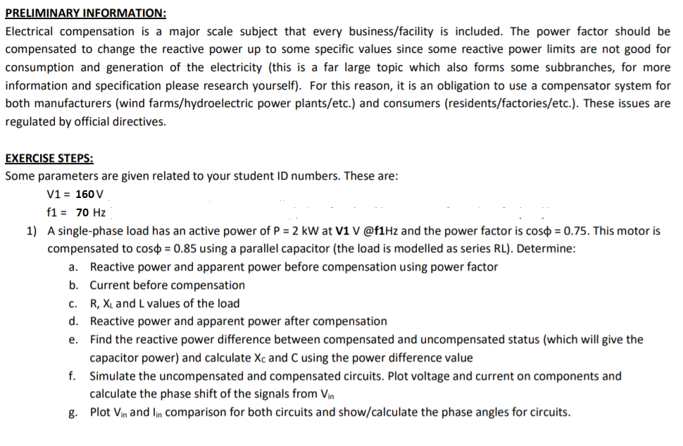
e. Find the reactive power difference between compensated and uncompensated status (which will give the capacitor power) and calculate Xc and C using the power difference value
e. Find the reactive power difference between compensated and uncompensated status (which will give the capacitor power) and calculate Xc and C using the power difference value
Introductory Circuit Analysis (13th Edition)
13th Edition
ISBN:9780133923605
Author:Robert L. Boylestad
Publisher:Robert L. Boylestad
Chapter1: Introduction
Section: Chapter Questions
Problem 1P: Visit your local library (at school or home) and describe the extent to which it provides literature...
Related questions
Concept explainers
Three-Phase Transformers
Three-segment transformers are a type of transformer used to transform voltages of electrical systems into three ranges. Two type transformers are shell-type transformer and core type transformer. In brief, it could be described because of the exquisite kinds of configurations.
Transformer
Ever since electricity has been created, people have started using it in its entirety. We see many types of Transformers in the neighborhoods. Some are smaller in size and some are very large. They are used according to their requirements. Many of us have seen the electrical transformer but they do not know what work they are engaged in.
Question
please just answer part e

Transcribed Image Text:PRELIMINARY INFORMATION:
Electrical compensation is a major scale subject that every business/facility is included. The power factor should be
compensated to change the reactive power up to some specific values since some reactive power limits are not good for
consumption and generation of the electricity (this is a far large topic which also forms some subbranches, for more
information and specification please research yourself). For this reason, it is an obligation to use a compensator system for
both manufacturers (wind farms/hydroelectric power plants/etc.) and consumers (residents/factories/etc.). These issues are
regulated by official directives.
EXERCISE STEPS:
Some parameters are given related to your student ID numbers. These are:
V1 = 160 V
f1 = 70 Hz
1) A single-phase load has an active power of P = 2 kW at V1 V @f1Hz and the power factor is coso = 0.75. This motor is
compensated to coso = 0.85 using a parallel capacitor (the load is modelled as series RL). Determine:
a. Reactive power and apparent power before compensation using power factor
b. Current before compensation
C.
R, XL and L values of the load
d. Reactive power and apparent power after compensation
e. Find the reactive power difference between compensated and uncompensated status (which will give the
capacitor power) and calculate Xc and C using the power difference value
f.
Simulate the uncompensated and compensated circuits. Plot voltage and current on components and
calculate the phase shift of the signals from Vin
g. Plot Vin and lin comparison for both circuits and show/calculate the phase angles for circuits.
Expert Solution
This question has been solved!
Explore an expertly crafted, step-by-step solution for a thorough understanding of key concepts.
Step by step
Solved in 2 steps with 1 images

Knowledge Booster
Learn more about
Need a deep-dive on the concept behind this application? Look no further. Learn more about this topic, electrical-engineering and related others by exploring similar questions and additional content below.Recommended textbooks for you

Introductory Circuit Analysis (13th Edition)
Electrical Engineering
ISBN:
9780133923605
Author:
Robert L. Boylestad
Publisher:
PEARSON

Delmar's Standard Textbook Of Electricity
Electrical Engineering
ISBN:
9781337900348
Author:
Stephen L. Herman
Publisher:
Cengage Learning

Programmable Logic Controllers
Electrical Engineering
ISBN:
9780073373843
Author:
Frank D. Petruzella
Publisher:
McGraw-Hill Education

Introductory Circuit Analysis (13th Edition)
Electrical Engineering
ISBN:
9780133923605
Author:
Robert L. Boylestad
Publisher:
PEARSON

Delmar's Standard Textbook Of Electricity
Electrical Engineering
ISBN:
9781337900348
Author:
Stephen L. Herman
Publisher:
Cengage Learning

Programmable Logic Controllers
Electrical Engineering
ISBN:
9780073373843
Author:
Frank D. Petruzella
Publisher:
McGraw-Hill Education

Fundamentals of Electric Circuits
Electrical Engineering
ISBN:
9780078028229
Author:
Charles K Alexander, Matthew Sadiku
Publisher:
McGraw-Hill Education

Electric Circuits. (11th Edition)
Electrical Engineering
ISBN:
9780134746968
Author:
James W. Nilsson, Susan Riedel
Publisher:
PEARSON

Engineering Electromagnetics
Electrical Engineering
ISBN:
9780078028151
Author:
Hayt, William H. (william Hart), Jr, BUCK, John A.
Publisher:
Mcgraw-hill Education,