QI-A) A sinusoidal vohage v,(t) = 20 sin wtis passed through half wavarectifier. Find 1) The period T. 2) The DC value of output voltage o- 3) The first harmonics of outpul voltage in.
QI-A) A sinusoidal vohage v,(t) = 20 sin wtis passed through half wavarectifier. Find 1) The period T. 2) The DC value of output voltage o- 3) The first harmonics of outpul voltage in.

Delmar's Standard Textbook Of Electricity
7th Edition
ISBN:9781337900348
Author:Stephen L. Herman
Publisher:Stephen L. Herman
Chapter17: Resistive-inductive Series Circuits
Section: Chapter Questions
Problem 2PP: Assume that the voltage drop across the resistor, ER, is 78 V, that the voltage drop across the...

Related questions
Question
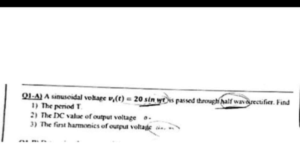
Transcribed Image Text:QI-A) A sinusoidal vohage v,(t) = 20 sin wtis passed through half waverectifier. Find
1) The period T.
2) The DC value of output voltage o-
3) The first harmonics of output voltage in.
Expert Solution
This question has been solved!
Explore an expertly crafted, step-by-step solution for a thorough understanding of key concepts.

Step by step
Solved in 2 steps with 2 images

Knowledge Booster


Learn more about
Need a deep-dive on the concept behind this application? Look no further. Learn more about this topic, electrical-engineering and related others by exploring similar questions and additional content below.Recommended textbooks for you
Delmar's Standard Textbook Of Electricity
Electrical Engineering
ISBN:
9781337900348
Author:
Stephen L. Herman
Publisher:
Cengage Learning
Delmar's Standard Textbook Of Electricity
Electrical Engineering
ISBN:
9781337900348
Author:
Stephen L. Herman
Publisher:
Cengage Learning