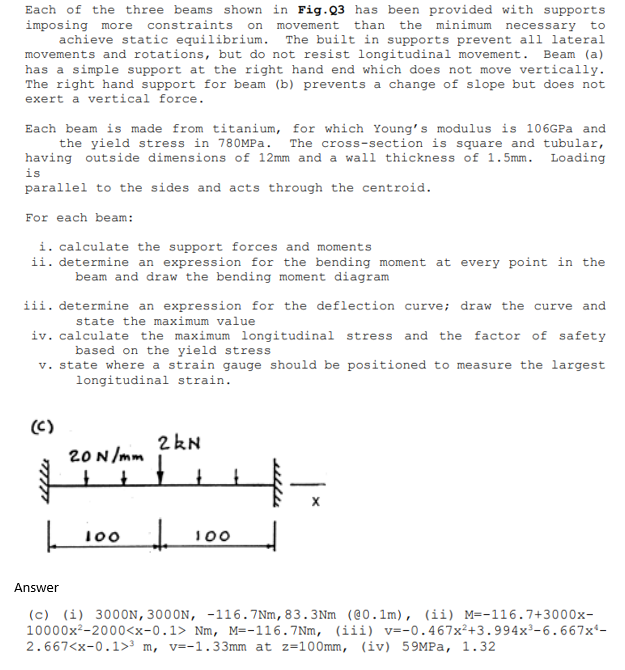
Each of the three beams shown in Fig. Q3 has been provided with supports imposing more constraints on movement than the minimum necessary to achieve static equilibrium. The built in supports prevent all lateral movements and rotations, but do not resist longitudinal movement. Beam (a) has a simple support at the right hand end which does not move vertically. The right hand support for beam (b) prevents a change of slope but does not exert a vertical force. Each beam is made from titanium, for which Young's modulus is 106GPa and the yield stress in 780MPa. The cross-section is square and tubular, having outside dimensions of 12mm and a wall thickness of 1.5mm. Loading is parallel to the sides and acts through the centroid. For each beam: i. calculate the support forces and moments ii. determine an expression for the bending moment at every point in the beam and draw the bending moment diagram iii. determine an expression for the deflection curve; draw the curve and state the maximum value iv. calculate the maximum longitudinal stress and the factor of safety based on the yield stress v. state where a strain gauge should be positioned to measure the largest longitudinal strain. (C) 20 N/mm + L 100 2 kN ↓ it 100
Each of the three beams shown in Fig. Q3 has been provided with supports imposing more constraints on movement than the minimum necessary to achieve static equilibrium. The built in supports prevent all lateral movements and rotations, but do not resist longitudinal movement. Beam (a) has a simple support at the right hand end which does not move vertically. The right hand support for beam (b) prevents a change of slope but does not exert a vertical force. Each beam is made from titanium, for which Young's modulus is 106GPa and the yield stress in 780MPa. The cross-section is square and tubular, having outside dimensions of 12mm and a wall thickness of 1.5mm. Loading is parallel to the sides and acts through the centroid. For each beam: i. calculate the support forces and moments ii. determine an expression for the bending moment at every point in the beam and draw the bending moment diagram iii. determine an expression for the deflection curve; draw the curve and state the maximum value iv. calculate the maximum longitudinal stress and the factor of safety based on the yield stress v. state where a strain gauge should be positioned to measure the largest longitudinal strain. (C) 20 N/mm + L 100 2 kN ↓ it 100

Chapter9: Application Of Influence Lines
Section: Chapter Questions
Problem 11P

Related questions

Question
Transcribed Image Text:Each of the three beams shown in Fig.Q3 has been provided with supports
imposing more constraints on movement than the minimum necessary to
achieve static equilibrium. The built in supports prevent all lateral
movements and rotations, but do not resist longitudinal movement. Beam (a)
has a simple support at the right hand end which does not move vertically.
The right hand support for beam (b) prevents a change of slope but does not
exert a vertical force.
Each beam is made from titanium, for which Young's modulus is 106GPa and
the yield stress in 780MPa. The cross-section is square and tubular,
having outside dimensions of 12mm and a wall thickness of 1.5mm. Loading.
is
parallel to the sides and acts through the centroid.
For each beam:
i. calculate the support forces and moments
ii. determine an expression for the bending moment at every point in the
beam and draw the bending moment diagram
iii. determine an expression for the deflection curve; draw the curve and
state the maximum value
iv. calculate the maximum longitudinal stress and the factor of safety
based on the yield stress
v. state where a strain gauge should be positioned to measure the largest
longitudinal strain.
(C)
T
20 N/mm
2kN
+
L 100 ite 100
Answer
(c) (i) 3000N, 3000N, -116.7Nm, 83.3Nm (@0.1m), (ii) M=-116.7+3000x-
10000x²-2000<x-0.1> Nm, M=-116.7Nm, (iii) v=-0.467x²+3.994x³-6.667x¹-
2.667<x-0.1>³ m, v=-1.33mm at z=100mm, (iv) 59MPa, 1.32
Expert Solution
This question has been solved!
Explore an expertly crafted, step-by-step solution for a thorough understanding of key concepts.

Step by step
Solved in 4 steps with 3 images

Knowledge Booster


Learn more about
Need a deep-dive on the concept behind this application? Look no further. Learn more about this topic, civil-engineering and related others by exploring similar questions and additional content below.Recommended textbooks for you