end pin supported beam has the cross-se

Mechanics of Materials (MindTap Course List)
9th Edition
ISBN:9781337093347
Author:Barry J. Goodno, James M. Gere
Publisher:Barry J. Goodno, James M. Gere
Chapter5: Stresses In Beams (basic Topics)
Section: Chapter Questions
Problem 5.6.14P: A cantilever beam AB with a circular cross section and length L = 750 mm supports a load P = 800 N...

Related questions
Question
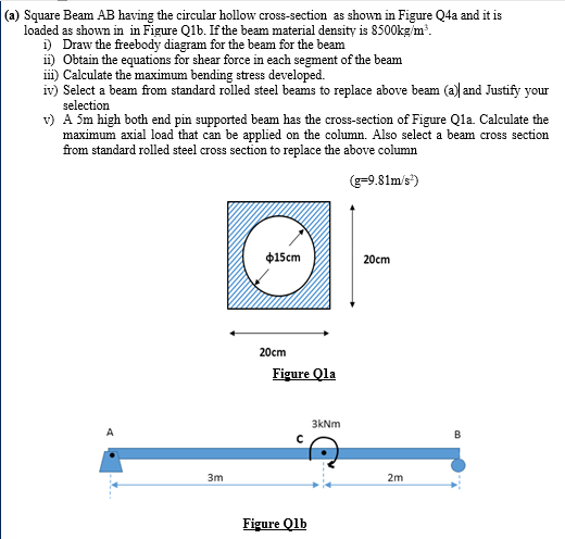
Transcribed Image Text:(a) Square Beam AB having the circular hollow cross-section as shown in Figure Q4a and it is
loaded as shown in in Figure Qlb. If the beam material density is 8500kg/m.
i) Draw the freebody diagram for the beam for the beam
ii) Obtain the equations for shear force in each segment of the beam
i) Calculate the maximum bending stress developed.
iv) Select a beam from standard rolled steel beams to replace above beam (a) and Justify your
selection
v) A 5m high both end pin supported beam has the cross-section of Figure Qla. Calculate the
maximum axial load that can be applied on the column. Also select a beam cross section
from standard rolled steel cross section to replace the above column
g=9.81m/s)
$15cm
20cm
20cm
Figure Qla
3kNm
A
3m
2m
Figure Qlb
Expert Solution
This question has been solved!
Explore an expertly crafted, step-by-step solution for a thorough understanding of key concepts.

Step by step
Solved in 2 steps with 2 images

Knowledge Booster


Learn more about
Need a deep-dive on the concept behind this application? Look no further. Learn more about this topic, mechanical-engineering and related others by exploring similar questions and additional content below.Recommended textbooks for you
Mechanics of Materials (MindTap Course List)
Mechanical Engineering
ISBN:
9781337093347
Author:
Barry J. Goodno, James M. Gere
Publisher:
Cengage Learning
Mechanics of Materials (MindTap Course List)
Mechanical Engineering
ISBN:
9781337093347
Author:
Barry J. Goodno, James M. Gere
Publisher:
Cengage Learning