EXPERIMENT PROCEDURE: Connect the parallel RLC circuit shown above and use the multimeter to measure all the currents in the circuit and record the values in the table below. To measure the phase shift of Ic, IL, and I, add a 1002 resistor in series with the component where you want to find the angle, and use the oscilloscope to compare the phase shift between E and the voltage across the 1002 resistor. Make sure that one end of the 1002 resistor is connected to ground. RESULTS: IR(rms) OR Ic(rms) ILurms) OL I (rms) 0° ASSIGNMENT: Calculate I, Ir, Ic, and IL (magnitude and angle in rms) using theoretical equations then compare with the measured values (Use E(rms) = 2.83VZ0° ).
EXPERIMENT PROCEDURE: Connect the parallel RLC circuit shown above and use the multimeter to measure all the currents in the circuit and record the values in the table below. To measure the phase shift of Ic, IL, and I, add a 1002 resistor in series with the component where you want to find the angle, and use the oscilloscope to compare the phase shift between E and the voltage across the 1002 resistor. Make sure that one end of the 1002 resistor is connected to ground. RESULTS: IR(rms) OR Ic(rms) ILurms) OL I (rms) 0° ASSIGNMENT: Calculate I, Ir, Ic, and IL (magnitude and angle in rms) using theoretical equations then compare with the measured values (Use E(rms) = 2.83VZ0° ).

Power System Analysis and Design (MindTap Course List)
6th Edition
ISBN:9781305632134
Author:J. Duncan Glover, Thomas Overbye, Mulukutla S. Sarma
Publisher:J. Duncan Glover, Thomas Overbye, Mulukutla S. Sarma
Chapter6: Power Flows
Section: Chapter Questions
Problem 6.61P

Related questions
Question
RLC PARALLEL CIRCUIT
Transcribed Image Text:RLC PARALLEL CIRCUIT
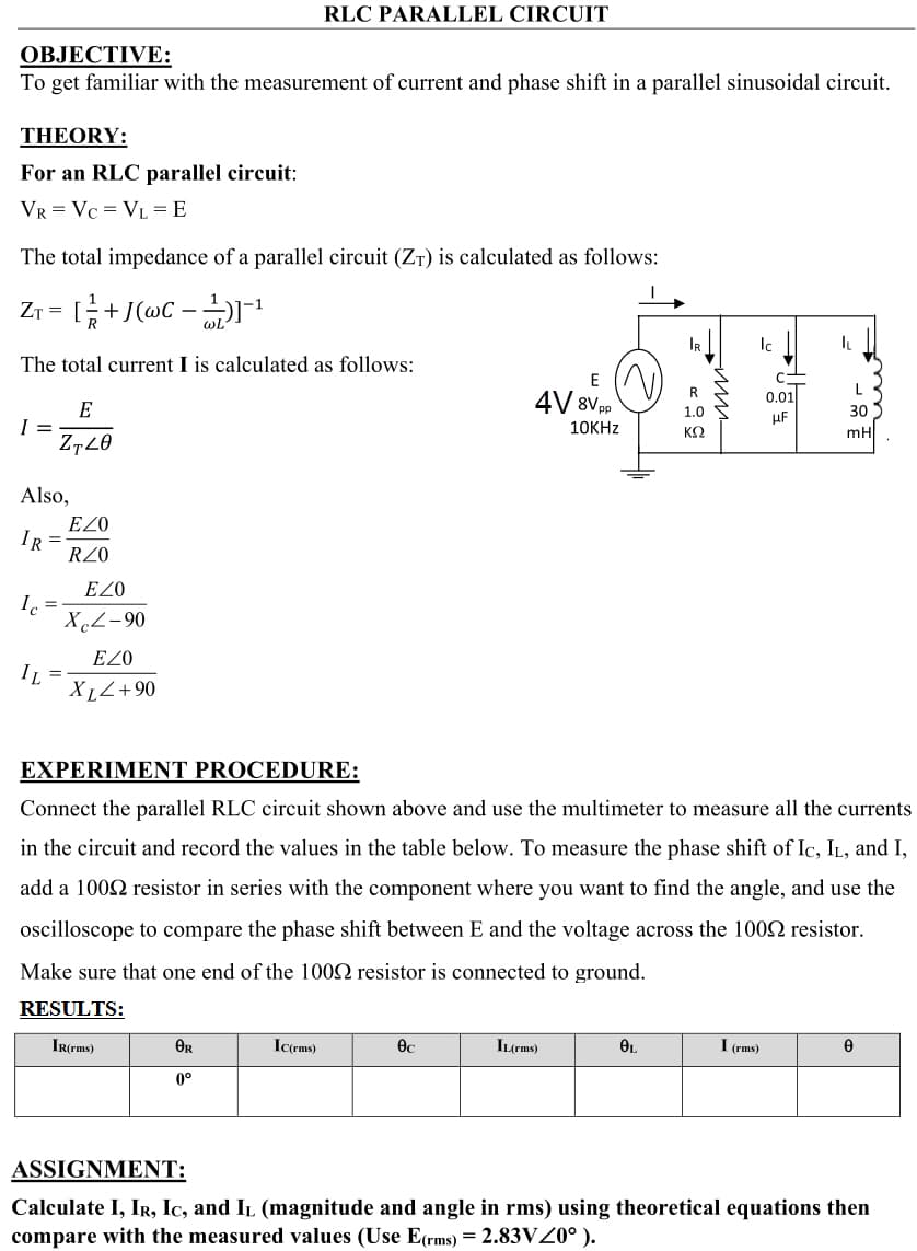
OBJECTIVE:
To get familiar with the measurement of current and phase shift in a parallel sinusoidal circuit.
THEORY:
For an RLC parallel circuit:
VR = Vc = VL = E
The total impedance of a parallel circuit (ZT) is calculated as follows:
Zr = +J(@C -
1
wL
The total current I is calculated as follows:
E
R
L
4V 8V pp
0.01
E
I =
Z720
1.0
30
uF
10KHZ
ΚΩ
mH
Also,
EZO
IR =
RZ0
EZO
I =
XcZ-90
EZ0
IL =
XL<+90
EXPERIMENT PROCEDURE:
Connect the parallel RLC circuit shown above and use the multimeter to measure all the currents
in the circuit and record the values in the table below. To measure the phase shift of Ic, IL, and I,
add a 1002 resistor in series with the component where you want to find the angle, and use the
oscilloscope to compare the phase shift between E and the voltage across the 1002 resistor.
Make sure that one end of the 1002 resistor is connected to ground.
RESULTS:
IR(rms)
OR
IC(rms)
IL(rms)
OL
I (rms)
0°
ASSIGNMENT:
Calculate I, Ir, Ic, and IL (magnitude and angle in rms) using theoretical equations then
compare with the measured values (Use E(rms) = 2.83VZ0° ).
Expert Solution
This question has been solved!
Explore an expertly crafted, step-by-step solution for a thorough understanding of key concepts.

Step by step
Solved in 2 steps with 2 images

Knowledge Booster


Learn more about
Need a deep-dive on the concept behind this application? Look no further. Learn more about this topic, electrical-engineering and related others by exploring similar questions and additional content below.Recommended textbooks for you
Power System Analysis and Design (MindTap Course …
Electrical Engineering
ISBN:
9781305632134
Author:
J. Duncan Glover, Thomas Overbye, Mulukutla S. Sarma
Publisher:
Cengage Learning
Power System Analysis and Design (MindTap Course …
Electrical Engineering
ISBN:
9781305632134
Author:
J. Duncan Glover, Thomas Overbye, Mulukutla S. Sarma
Publisher:
Cengage Learning