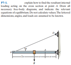
explain how to find the resultant internal loading acting on the cross section at point A. Draw all necessary free-body diagrams, and indicate the relevant equations of equilibrium. Do not calculate values The lettered dimensions, angles, and loads are assumed to be known. P7-1.
Q: For the lightweight truss shown 9 kN 12 kN 9 kN В H G F 30° A 10 m 10 m 10 m 10 m ( all 30°, 60°,…
A: Due to symmetry, RA+RE=12(9+12+9)=15 kN
Q: Determine the shape factor for the member having the tubular cross section.
A:
Q: 1200 N/m y 1700 N/m -6 m- -8 m-
A: For UVL : R1 = WL/2 = 1200 * 6 / 2 = 3600 N X1 = 2L/3 = 2 * 6 /3 = 4 m For trapezoidal load : R2 =…
Q: The L-shaped frame is made from two segments, each of length L and flexural stiffness EI. If it is…
A: Given Length = L Flexural stiffness = EI Weight = w To find The horizontal displacement of point C
Q: explain how to find the resultant internal loading acting on the cross section at point A. Draw all…
A: From the given figure and equation of equilibrium, the vector analysis is applied and can be written…
Q: the bar element's linear shape, or interpolation ons are: N1= 1-x/L, and N2= x/L (where L is the ent…
A:
Q: The L-shaped frame is made from two segments, each of length L and flexural stiffness EI. If it is…
A: The moment due to distributed load about the point B is The vertical displacement of the point B is…
Q: P7-5. The lever is held to the fixed shaft using the pin AB. If the couple is applied to the lever,…
A:
Q: F7-3. Determine the internal normal force, shear force, and bending moment at point C in the beam.…
A: Draw the FBD of the given problem. Apply equilibrium condition. Determine the moment about point B.
Q: 7-13. The blade of the hacksaw is subjected to a pretension force of F-100 N. Determine the…
A: Given data: *The pretension force subjected in the blade of the hack saw is F=100 N. *The vertical…
Q: 7-14. The boom DF of the jib crane and the column DE have a uniform weight of 750 N/m. If the hoist…
A: Draw the free-body diagram of the section AF.
Q: P7-3. Determine the largest internal normal force in the bar. D. 10 kN 5 kN 2 kN 6 kN
A: Determine the normal force in the bar: Apply the conditions of the equilibrium: Where, FX is the…
Q: 7-17. Determine the resultant internal loadings on the cross section through point D. Assume the…
A:
Q: All problem solutions must include an FBD. u 5-10. Determine the components of the support reaction…
A: As per given question We have to determine the support reaction at the fixed supports A
Q: 04m d=0.15m D
A:
Q: P7-2. determine the largest internal shear force resisted by the bolt. Include all necessary…
A: Consider the free body diagram of the middle panel as shown below. The 6 kN force is balanced by…
Q: Determine the resultant of the line load acting on the beam ABC. 1200 Ib/ft y 1700 Ib/ft C 6 ft -8…
A: find the resultant force of the given distributed load.
Q: 7-23. The metal stud punch is subjected to a force of 120 N on the handle. Determine the magnitude…
A:
Q: 6-30. The steel plate is 0.3 m thick and has a density of 7850 kg/m. Determine the location of its…
A: Given data The density of steel plate,ρ is 7850 kg/m3. Thickness of steel plate, t is 3 m. Determine…
Q: 9-22. The post is made of Douglas fir and has a diameter of 100 mm. If it is subjected to the load…
A: Given data To determine the force F needed at the bottom end needed for equilibrium.
Q: I1-63. The shaft is supported by smooth journal bearings at A and B that only exert vertical…
A:
Q: Railroad ties must be designed to resist large shear loadings. If the tie is subjected to the 34-kip…
A: Write the equation for total force acting on the tie due to the uniformly distributed reaction.…
Q: 7-11. Ihe ocam supporis the distributed load shown. Determine the resultant internal loadings acting…
A: Draw the free body diagram and find the reactions: Note that the total load on the beam is given by…
Q: P7-6. The single-V butt joint transmits the force of 5 kN from one bar to the other. Determine the…
A: Given data The joint type is: Single-V butt joint Force transfer from the bar: 5 kN Adding the…
Q: 7-3. The shaft is supported by a smooth thrust bearing at A and a smooth journal bearing at B.…
A: Draw the FBD for the above problem.
Q: 7-25. Determine resultant internal loadings acting on section a-a and section b-b. Each section…
A: Given data: Force and dimensions in the figure. Assuming reaction forces at A in vertical…
Q: "9-8. The truss is made of three A-36 steel members. each having a cross-sectional area of 400 mm.…
A: Given data: Cross-sectional area is A = 400 mm2. The displacement of roller is x = 0.2 mm. Taking…
Q: The bent pipe ABCD lies in the ry-plane and bends through 90° at C and supports a hanging weight W…
A: Draw the free body diagram of the bent pipe:
Q: 5-107 Determine the resultant R of the system of dis- tributed loads on the beam of Fig. P5-107 and…
A: Consider the Section 1 from support A till the 4 ft length (where the parabolic loading ends). The…
Q: 7-7. Determine the resultant internal loadings in the beam at cross sections through points D and E.…
A: Answer : In the given figure we can observe that end A is having roller support while end C is…
Q: The shaft is supported by a smooth thrust bearing at B and a journal bearing at C. Determine the…
A: Given data: The load acting at D point is PD = 800 lb The load acting at A point is PA = 400 lb The…
Q: explain how to find the resultant internal loading acting on the cross section at point A. Draw all…
A: The free body diagram is shown below, Taking moment about point B, ∑MB=0RC×a-Psinθ×2a=0RC=2Psinθ…
Q: P1-4. Determine the internal normal force at section A if the rod is subjected to the external…
A:
Q: 7-10. The beam supports the distributed load shown. Determine the resultant internal loadings acting…
A: Given Data: The triangular load varies from w1 = 4 kN/m to w2 =0. The span of the beam is L = 6 m.…
Q: *R8-4. The wires each have a diameter of 12 mm, length of 0.6 m, and are made from 304 stainless…
A:
Q: Determine the internal resisting forces and moment trans- mitted by section aa in B 30 750 Ib 30 in.…
A: Given: The radius of curvature, R= 30 in force at the end, FP=750 lb at an angle 30o The radius of…
Q: Determine the member end moments at b, Mba and Mbc, in the following structure. EI constant 300kN 2m…
A: Given dataP=300kNRoller support at C which exhibit only vertial force
Q: The beam is subjected to the distributed load and the couple shown. If Mis slowly increased starting…
A: Answer: Mo = 5030.67 lb•ft.
Q: Determine ALL the internal loadings acting on a) the section a-a, the section b-b. Hint: You will…
A:
Q: 9-27. The linkage is made of two pin-connected A-36 steel members, each having a cross-sectional…
A: Given Data Cross-sectional area =1000mm2=1000×10-6m=10-3m Vertical force,P=250KN Young modulus of…
Q: *7-16. Determine the resultant internal loadings on the cross section through point C. Assume the…
A: Given data: A simply supported beam with point load and UVL.
Q: 7-5. Determine the resultant internal loadings at eross sections at points E and Fon the assembly.…
A: Given: All the dimensions are provided in the figure Drawing the free body diagram to determine the…
Q: 7-15. The force F- 400 N acts on the gear tooth. Determine the resultant internal loadings on the…
A: Given: The magnitude of the applied force is F=400 N. The free-body diagram of the tooth is, Here…
Q: 3)Find the true magnitude and direction of the forces in each member AC,CD Fig4.3 6' -5- +y 8' A.…
A:
Q: Wo -L/2– -L/2- Fig. P17-16
A: Deflection at B by Modified Castigliano's theorem.putting an imaginary force P at B.…
Q: The man has a mass of 100 kg and center of mass at G. If he holds himself in the position shown,…
A: givenmass =100kgeach bar has diameter d=25mm
Q: The metal stud punch is subjected to a force of 120 N on the handle. determine the magnitude of the…
A: Moment acting about point A FBCcos3050=120200+300FBC=1.39 kN Vertical forces…
Q: The solid rod has a radius of 0.1 m. If it is subjee to the forces of 50 kN and 80 kN, determine the…
A:
Q: Draw the free-body diagram for the following problem. The crane and boom shown.
A: for the given figure we need to determine its free body diagram
Q: P7-4. Determine the internal normal force at section A if the rod is subjected to the external…
A: givenexternal uniformally distributed load W=8kN/mlength of cantilever beam L=5mbeam shown as below…
Trending now
This is a popular solution!
Step by step
Solved in 3 steps with 3 images
- Include the Free body diagram ,and don't provide previously solved answers.Based on the information given on the free body diagram , find the value of Ax, Ay and N.: The cylindrical pressure vessel with hemispherical end-caps is made of steel. The vessel has a uniform thickness of 0.44mm and an outer diameter of 9.768mm. When the vessel is pressurized to 0.088 MPa, determine the change in the overall length of the vessel. Use E = 200 GPa and µ = 0.3 for steel. Neglect localized bending.R=22
- Before the uniform distributed load is applied to the beam, there is a small gap of 0.2 mm between the beam and the post at B. Determine the support reactions at A, B, and C. The post at B has a diameter of 40 mm, and themoment of inertia of the beam is I = 875(106) mm4. The post and the beam are made of material having a modulus of elasticity of E = 200 GPa.The aluminum block has a rectangular cross section and is subjected to an axial compressive force of 8 kip. If the 1.5-in. side changed its length to 1.500132 in., determine the Poisson's ratio. Assume modulus of elasticity (E) = 10 x 10^3 ksi indicate the free body diagramThe A-36 steel bar consists of two segments, one ofcircular cross section of radius r, and one of square crosssection. If the bar is subjected to the axial loading of P,determine the dimensions a of the square segment so thatthe strain energy within the square segment is the same asin the circular segment.
- Draw the Free Body Diagram and solve the problemThe assembly below consists of a steel rod CB and an aluminium rod BA, each having a diameter of 12 mm. If the rod is subjected to the axial loadings at A and at the coupling B, determine the displacement of the coupling B and the end A. The unstretched length of each segment is shown below. Neglect the size of the connections at B and C, and assume that they are rigid. Est = 200 GPa, Eal = 70 GPa.The rod has a circular cross section. If it is made of an elastic perfectly plastic material, determine the shape factor for the rod.
- The fr a me A BCD shown in the heure is squeezed by two collinear forces P acting at points A and D. What is the decrease ê in the distance between points A and D when the loads P are applied? (The flexural rigidity EI is constant throughout the frame,) Note: Disregard the effects of axial deformations and consider only the effects of bending due to the loads P.Please show the complete solution and draw the free body diagram correctlyThe three-bar truss in Fig. a is subjected to a horizontal force of 5 kip. If the cross-sectional area of each member is 0.20 in2, determine the horizontal displacement at point B. E = 29(103) ksi.