F) Answer the following Questions: Battery 1) The following circuit has a problem. Switch #1 is able to control lamp #1, but lamp #2 never comes on no matter what is done with switch #2: TP1 TP4 TP2 Switch #1 Lamp #1 TP5 Statues Battery is dead Switch #2 failed open Switch #1 failed shorted Open wire between test points 1 and 2 (between TP1 and TP2). TP3 2) According circuit above if there are some faults write the output for each situation Open wire between test points 5 and 6 (between TP5 and TP6) TP6 Switch #2 Lamp #2 The output
F) Answer the following Questions: Battery 1) The following circuit has a problem. Switch #1 is able to control lamp #1, but lamp #2 never comes on no matter what is done with switch #2: TP1 TP4 TP2 Switch #1 Lamp #1 TP5 Statues Battery is dead Switch #2 failed open Switch #1 failed shorted Open wire between test points 1 and 2 (between TP1 and TP2). TP3 2) According circuit above if there are some faults write the output for each situation Open wire between test points 5 and 6 (between TP5 and TP6) TP6 Switch #2 Lamp #2 The output

Delmar's Standard Textbook Of Electricity
7th Edition
ISBN:9781337900348
Author:Stephen L. Herman
Publisher:Stephen L. Herman
Chapter2: Electrical Quantities And Ohm’s Law
Section: Chapter Questions
Problem 3PA: You are an electrician installing the wiring in a new home. The homeowner desires that a ceiling fan...

Related questions

Question
Transcribed Image Text:F) Answer the following Questions:
Battery
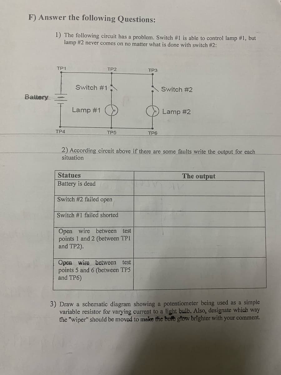
1) The following circuit has a problem. Switch #1 is able to control lamp #1, but
lamp #2 never comes on no matter what is done with switch #2:
TP1
TP4
Switch #1
Lamp #1
TP2
TP5
Statues
Battery is dead
Switch #2 failed open
Switch #1 failed shorted
Open wire between test
points 1 and 2 (between TP1
and TP2).
TP3
2) According circuit above if there are some faults write the output for each
situation
Open wire between test
points 5 and 6 (between TP5
and TP6)
TP6
Switch #2
Lamp #2
The output
3) Draw a schematic diagram showing a potentiometer being used as a simple
variable resistor for varying current to a light bulb. Also, designate which way
the "wiper" should be moved to make the bulb glow brighter with your comment.
Expert Solution
This question has been solved!
Explore an expertly crafted, step-by-step solution for a thorough understanding of key concepts.

This is a popular solution!

Trending now
This is a popular solution!

Step by step
Solved in 3 steps with 1 images

Knowledge Booster


Learn more about
Need a deep-dive on the concept behind this application? Look no further. Learn more about this topic, electrical-engineering and related others by exploring similar questions and additional content below.Recommended textbooks for you
Delmar's Standard Textbook Of Electricity
Electrical Engineering
ISBN:
9781337900348
Author:
Stephen L. Herman
Publisher:
Cengage Learning

EBK ELECTRICAL WIRING RESIDENTIAL
Electrical Engineering
ISBN:
9781337516549
Author:
Simmons
Publisher:
CENGAGE LEARNING - CONSIGNMENT
Delmar's Standard Textbook Of Electricity
Electrical Engineering
ISBN:
9781337900348
Author:
Stephen L. Herman
Publisher:
Cengage Learning
EBK ELECTRICAL WIRING RESIDENTIAL
Electrical Engineering
ISBN:
9781337516549
Author:
Simmons
Publisher:
CENGAGE LEARNING - CONSIGNMENT