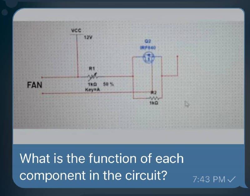
FAN VCC 12V R1 1KG 50 % Key=A 02 IRF840 R2 www 180


Q: 2. Suppose a voltage v(t) = A sin (300t + A1°) volts is applied to a single phase load and the…
A:
Q: 50-Ω R and 70-Ω XL are in series with 120V applied. Find the impedance, total current, power factor,…
A:
Q: V = 0.5 V '10 ΚΩ • 10 ΚΩ + να Activate Windo ΑΛΛ 200 ΚΩ
A:
Q: EXPERIMENT #4: BJT VERIFICATION MEMBERS: OBJECTIVES: Verify the integrity of the junctions of a ppp…
A: BJT- It is one of the type of transistor. Bipolar Junction Transistor is known as a bipolar because…
Q: t w = 10000, the system H(s) = 10000*((s+100)(s+100))/((s+1000)(s+100000)) has a gain of: O A. None…
A:
Q: Ceiling fan is a a. Single Phase Induction Motor b. DC Motor c. Three Phase Induction Motor d.…
A: Motor and its application: Motor Applications Single phase induction motor Small fans,…
Q: What is the power absorbed in Watts by a resistor with resistance of 5.00 is connected to a voltage…
A: Given: Resistor with resistance, R=5 Ω Voltage source with voltage, V = 2.7 V
Q: 3.80 In the circuit as shown in figure, the switch is closed at t= 0. The current through the…
A:
Q: 4. Write, in the spaces provided, the control, or controls, that perform each of the following…
A: 4). The control which is used to perform the below given functions is explained in below steps. a)…
Q: Reduce to a single transfer function: R(S)- S S 200 S S 115 C(s)
A: Given problem can be solved by block reduction technique as stated below.
Q: 4. A) Reduce the given circuit to the fewest possible components thru series/parallel combinations…
A: The reduced circuit can be obtained by considering the parallel and series connected elements. The…
Q: 3. Use four NAND gates only (without an inverter). This can be done by connecting the output of the…
A: (3) =DC'.C'=DC+C'=D+C'C+C'=D+C'
Q: A 132 kV circuit breaker interrupts the fault current flowing into a symmetrical three-phase to each…
A: Given A 132 kV circuit breaker interrupts the fault current flowing into a symmetrical three-phase…
Q: 4.41) If the Q- factor of a coil at resonant frequency of 1.5 MHz is 150 for a series resonant…
A:
Q: For a series R-L circuit i(t) = √2 sin (wt-45°) If @L=12, the value of R is (a) 1 Ω (b) 3 Ω (c) 13 Ω…
A:
Q: Solve the base current (IB) of Figure 611. VCC 8.92 UA 2.56 UA 10.74 UA 1.07 uA R1 680k 18V R2…
A: Consider the given diagram for the npn transistor. The input resistance is of 680 kohm. The Vcc is…
Q: Solve the emitter voltage (VE) of Figure 612. VCC 8V Beta = 110 R2 ww 3.9ΚΩ Figure 612 0.7V -1.48V…
A:
Q: 3.29) in the network shown below, it is given that v = 1V and dv/dt = -10 V/s at a time t, where t…
A: Given circuit, Where, v=1 Vdvdt=-10 Vs
Q: For a series R-L circuit i(t) = √2 sin (cut-45°) If @L=10, the value of R is (a) 1 Ω (b) 3 Ω (c) √3…
A: Given a series R-L circuit has, Current, it=2sin ωt-45° ωL=1 Ω
Q: You are designing a filter and the design equations produce a resistor value of 1 KQ and a capacitor…
A: Brief description: In the above given question they have mentioned a filter circuit. For the given…
Q: Given an Ideal OP-AMP, what is the output voltage if the input voltage is Vi=0.9 V,R1 = 220 2 and…
A:
Q: For the root locus shown below, the break in point is -25 -20 -15 -10 -5 03 -18 -10+9i -10 O
A: - Root locus is the technique to analyse the stability of the closed loop control system.
Q: +1 R 0.5 0.5 H Figure 1 a. What is the direct transmission gain from input R to output C? b. What is…
A: Here we discuss about the concepts related to the block diagram of the control system. NOTE :-…
Q: What is the mean of wiring
A: Wiring is the term used for the supply system design, connection, and protection schemes employed…
Q: For each circumstance, explain the SCR's behavior: • If the current at the anode is less than the…
A: The latching and holding currents of an SCR (Silicon Controlled Rectifier) are first explained.…
Q: A :) Given the following model in SIMULINK : Write the equation of relationship between output to…
A: The output to the input relationship can be obtained by reducing the network using block diagram…
Q: Solve for VE of Figure 43. VCC T21V V₁ R1 3500ΚΩ R2 $2.1kQ Q1 Beta = 110 R3 {1.2ΚΩ Figure 43 Vc VE
A:
Q: At w = 4000, the system H(s) = 10000*((s+100)(s+100))/((s+10000)(s+10000)) has a gain of: O A. 76 dB…
A: This question belongs to control system . It is based on the concept of calculation of gain of the…
Q: h no load? Fm-2 in-1h s/rad and km-15 in-1h/y (T] =KmVm-Emi) '
A: Solution- Given,Fm = 2 in-lbs/radKm = 15 in-lb/radωs = 150 rad/secinput voltage Vin = FKm ×ωs
Q: Given an Ideal OP-AMP with the following parameters: R1 = 680 2, R2 = 100 92, R3 = 1802, Rf = 2.7…
A:
Q: Use Routh's stability criterion to investigate the stability
A: In this question we need to Use Routh's stability criterion to investigate the stability.
Q: Solve the le (Emitter current) of the given circuit. Vcc=20 V 1.37 MA 1.02 MA 6.22 MA www 220 ΚΩΙ 56…
A: We need to find out the emitter current for given circuit
Q: A 15.0-F parallel-plate capacitor is connect in series to a 24.0-volt battery. When potential energy…
A: Given, A parallel plate capacitor with Capacitance, C=15.0 μF Supply, VS=24.0 V
Q: Q2j Consider the function: (s) = 1−e-T² S X(s) = Show that s = 0 is not a pole of X(s).
A:
Q: Design an ammeter to measure 100mA using a 50μA PMMC meter movement with internal resistance 3k Ω.…
A: Consider the current to be measured is of 200 mA The range of the PMMC is 50μA The internal…
Q: eedback control system characteristic equation is shown below +5² +5 +10=0 in the Routh Hurwitz test…
A: Routh hurwitz criteria is used to test stability of closed loop system. In this routh table is…
Q: Solve the collector voltage of an emitter stabilized bias circuit with Vcc=18V, RB-720k ohms,…
A:
Q: A solenoid is designed to produce a magnetic field of 2.50x10⁻² T at its center. It has a radius of…
A: We need to find out number of turns per unit length.
Q: A :) Given the following model in SIMULINK : Write the equation of relationship between output to…
A: The given block diagram can be reduced by considering the parallel and series connected block first…
Q: Design Problem: A pattern recognizer with a 1-bit output Y accepts a 1-bit input X. Y becomes 1 only…
A: “Since you have posted a question with multiple sub-parts, we will solve first three subparts for…
Q: Question 4 Using the appropriate method in generating the "final" Routh Table, enter the elements in…
A: We need to find out Routh hurtwiz table for given system
Q: A 15.0-F parallel-plate capacitor is connect in series to a 24.0-volt battery. When electrostatic…
A:
Q: A 10-ohm resistor and 10 H inductor are connected in series across a source of 12 V. If the current…
A:
Q: A wire is 21.0 m long at 3.50°C and is 1.66 cm longer at 36.5°C. Find the wire's coefficient of…
A: Given, A wire has L0=21.0 m at T0=3.50°CL=1.66 cm at T=36.5° C
Q: Determine I1, I2, Vo and V₁. Figure 1
A: As per the guidelines,we are supposed to answer only first question. Please repost the remaining as…
Q: Determine the maximum current lz if Vz=8 V Pzmax=150mW * R www 470 02 4 24 V 28.3 mA 20 mA 18.75 mA…
A: Given the diagram for the zener circuit. The zener voltage is 8 V. The zener power is 150 mW.
Q: Reduce to a single transfer function: R(s) G₁(s) G₂(s) 1 -1 -1 1 G₁(s) G₁(s) -1 -1 C(s)
A: The above signal flow graph is solved by using Mason's gain formula. By Mason's gain formula, the…
Q: A basic D’Arsonval movement with a full-scale deflection of 50μA and an interval resistance of 1800Ω…
A: This question belongs to measurements and instrumentation . It is based on the concept of multi…
Q: 1. Compare the performance in terms of their efficiency the common base, common emitter, and common…
A: Since you have posted a question with multiple sub-parts, we will solve first three subparts for…
Q: A basic D’Arsonval movement with a full-scale deflection of 50μA and internal resistance of 500Ω is…
A:

Step by step
Solved in 2 steps


- Given Variables: I, Vtotal, VR1, VD1 (B1=12V, R1=220 Ω)Are the following statements correct or wrong? Justify your answer. (a) GTO requires very high current applied to its gate to be turn ofr. (b) IGBT is a current driven device. (c) IGBT is more efficient than BJT in high power applications. (d) Thyristors are used only for low voltage, low current applications. (e) MOSFETS are used for low frequency applications.2)Convert 11011010100100012 to hexadecimal. A)895B B)CA11 C)53AC1 D)DA91
- A 12-bit counting converter with VFS = 5 V and fc = 1 MHz has an input voltage VX = 3.760 V. (a) What is the output code? What is the conversiontime TT for this value of VX if fc = 1 MHz? (b) Repeat for VX = 4.333 V.For the circuit below if selection lines S2S1S0=011 the output Z will be ____, if S2S1S0=100, Z will be ____, if S2S1S0=001, Z will be ____.Design a shift resistor to store 101101. Show all steps of how you store the data using shift resistor.
- Perform the design that performs the MOD (4) function with ( JK ) type counters.The resolution of the ADC unit with the reference voltage value of 3V is set to 8 bits. If the voltage level applied to the ADC input is 1.67 V, what is the numerical value read? For numbers with commas, take 4 digits after commas.EENG226 SIGNALS AND SYSTEMS PLEASE SOLVE C.D.E
- EENG226 SIGNALS AND SYSTEMS PLEASE SOLVE c d e1. Convert: 0.FF16 = _____________ 10 2. Convert from Binary to Gray code: 11010100102 = _______________________ Gray code 3. BCD Addition: 7892 + 797 = 4. Signed Binary Operation: -85310 - 39810 I need answer ASAP. Thank you so muccch!!PLEASE ASAP?? Mention the segments that must be logical 1 on the BCD seven segment common cathode to produce displays 9, C, d, and F!