FEC420 Assignment 1. A 200-km, 230-kv, 60-He three-phase line has a positive-sequence series impedance z 0:00 +10:48 R/km and a positive-sequence shunt admittance ym 13:33 p5/kum. At full load, the line delivers 250 MW at 0.99 pt. lagging and at 220 kV. Using the nominal circuit, calculate: (a) the ABCD parameters, (b) the sending and voltage and current, and (c) the percent voltage regulation 2. The 500-, 60-iz three-phase completely transposed overhead line having three ACSR 1113-kemil (556.50 mm) conductors per bundle, with 0.5 m between conductors in the bundle. The horizontal phase spacings between bundle centers are 10, 10, and 20 m. has a 300-km length. Calculate () 2. (b) y and (c) the exact ABCD parameters for this line. Assume a 30°C conductor temperature. Note: The Aluminum Electrical Conductor Handbook lists a de resistance of 0.01558 ohm per 1000 ft (or 0.05112 ohm per km) at 20°C and a 60-lite resistance of 0.0956 ohm per mile (or 0.0594 ohm per km) at 50°C for the all-aluminum Marigold conductor, which has 61 strands and whose stre is 564 mm2 or 1113 kemil. 3 4 230-4V, 100-km, 60-He three-phase overhead transmission line with a rated current of 900 A/phase has a series impedance z 0:088 +10:465 2/km and a shunt admittance y-18.324 ms/km. (a) Obtain the nominal equivalent creat in normal units and is per unit on a base of 100 MVA (three phase) and 230 kV (line-to-line) (b) Determine the three-phase rated MVA of the Ine. (c) Compute the ABCD parameters (d) Calculate the SIL 4. Consider the simplified electric power system shown below for which the power flow solution can be obtained without resorting to iterative techniques. (a) Compute the elements of the bus admittance matrix Y. (b) Calculate the phase angle 82 by using the real power equation at bus 2 (veltage-
FEC420 Assignment 1. A 200-km, 230-kv, 60-He three-phase line has a positive-sequence series impedance z 0:00 +10:48 R/km and a positive-sequence shunt admittance ym 13:33 p5/kum. At full load, the line delivers 250 MW at 0.99 pt. lagging and at 220 kV. Using the nominal circuit, calculate: (a) the ABCD parameters, (b) the sending and voltage and current, and (c) the percent voltage regulation 2. The 500-, 60-iz three-phase completely transposed overhead line having three ACSR 1113-kemil (556.50 mm) conductors per bundle, with 0.5 m between conductors in the bundle. The horizontal phase spacings between bundle centers are 10, 10, and 20 m. has a 300-km length. Calculate () 2. (b) y and (c) the exact ABCD parameters for this line. Assume a 30°C conductor temperature. Note: The Aluminum Electrical Conductor Handbook lists a de resistance of 0.01558 ohm per 1000 ft (or 0.05112 ohm per km) at 20°C and a 60-lite resistance of 0.0956 ohm per mile (or 0.0594 ohm per km) at 50°C for the all-aluminum Marigold conductor, which has 61 strands and whose stre is 564 mm2 or 1113 kemil. 3 4 230-4V, 100-km, 60-He three-phase overhead transmission line with a rated current of 900 A/phase has a series impedance z 0:088 +10:465 2/km and a shunt admittance y-18.324 ms/km. (a) Obtain the nominal equivalent creat in normal units and is per unit on a base of 100 MVA (three phase) and 230 kV (line-to-line) (b) Determine the three-phase rated MVA of the Ine. (c) Compute the ABCD parameters (d) Calculate the SIL 4. Consider the simplified electric power system shown below for which the power flow solution can be obtained without resorting to iterative techniques. (a) Compute the elements of the bus admittance matrix Y. (b) Calculate the phase angle 82 by using the real power equation at bus 2 (veltage-

Power System Analysis and Design (MindTap Course List)
6th Edition
ISBN:9781305632134
Author:J. Duncan Glover, Thomas Overbye, Mulukutla S. Sarma
Publisher:J. Duncan Glover, Thomas Overbye, Mulukutla S. Sarma
Chapter5: Transmission Lines: Steady-state Operation
Section: Chapter Questions
Problem 5.2P: A 200-km, 230-kV, 60-Hz, three-phase line has a positive-sequence series impedance z=0.08+j0.48/km...

Related questions
Question
Question 3
Transcribed Image Text:4:28
←
EEC420_2022_Mih_... Q
FFC420 Assignment
1. A 200-km, 230-kV. 60-Hz three-phase line has a positive-sequence series impedance z= 0:00 +10:48
n/km and a positive-sequence shunt admittance y 13:33 µS/km. At full load, the line delivers 250 MW at
0.99 p.t. lagging and at 220 kV. Using the nominal x circuit, calculate: (a) the ABCD parameters, (b) the
sending end voltage and current, and (c) the percent voltage regulation
2. The 500-kv, 60-Hz three-phase completely transposed overhead line having three ACSR 1113-kemil
(556.50 mm) conductors per bundle, with 0.5 m between conductors in the bundle. The horizontal
phase spacings between bundle centers are 10, 10, and 20 m. has a 300-km length. Calculate (a) Z. (b) y/
and (c) the exact ABCD parameters for this line. Assume a 50°C conductor temperature Note: The
Aluminum Electrical Conductor Handbook lists a de resistance of 0.01558 ohm per 1000 ft (or 0.05112
ohm per km) at 20°C and a 60-Hz resistance of 0.0956 ohm per mile (or 0.0994 ohm per km) at 50°C for
the all-aluminum Marigold conductor, which has 61 strands and whose size is 564 mm2 or 1113 kcmil.
3. A 230-kV, 100-km, 60-Hz three-phase overhead transmission line with a rated current of 900 A/phase
has a series impedance z 0:088 +10:465 /km and a shunt admittance y-3.524 m5/km. (a) Obtain
the nominal a equivalent circuit in normal units and in per unit on a base of 100 MVA (three phase) and
230 kV (line-to-line). (b) Determine the three-phase rated MVA of the Ine. (c) Compute the ABCD
parameters (d) Calculate the SIL
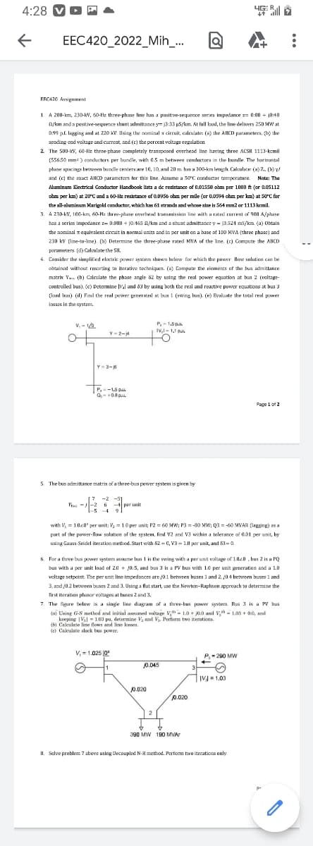
4. Consider the simplified electric power system shown below for which the power flow solution can be
obtained without resorting to iterative techniques. (a) Compute the elements of the bus admittance
matrix Y. (b) Calculate the phase angle 82 by using the real power equation at bus 2 (voltage-
controlled bus). (c) Determine V₂ and 63 by using both the real and reactive power equations at bus 3
(load bus). (d) Find the real power generated at bus 1 (swing bus). (e) Evaluate the total real power
losses in the system.
V. -1/0
P.-1.5 pu
IV,1-1,1 p
Y-2-j4
Y-3-16
P,-1.5 p
Q-+0.8
Page 1 of 2
5. The bus admittance matrix of a three-bus power system is given by
[7 -2
Yu-2 6-4 per unit
-5-49
-&
1
with V,
1.020 per unit: V₂ = 1.0 per unit; P2 = 60 MW; P380 MW: 03-60 MVAR (lagging) as a
part of the power-flow solution of the system, find V2 and V3 within a tolerance of 0.01 per unit, by
using Gauss-Seidel iteration method. Start with 82-0, V3-1.0 per unit, and 83-0
6. For a three bus power system assume bus 1 is the swing with a per unit voltage of 1.020, bus 2 is a PQ
bus with a per unit load of 2.0+ 0:5, and bus 3 is a PV bus with 10 per unit generation and a 1.0
voltage setpoint. The per unit line impedances are j0.1 between buses 1 and 2. 10.4 between buses 1 and
3, and 10.2 between buses 2 and 3. Using a flat start, use the Newton-Raphson approach to determine the
first iteration phasor voltages at buses 2 and 3.
7. The figure below is a single line diagram of a three-bus power system. Bus 3 is a PV bus
(n) Using G-S method and initial assumed voltage V1.0+ 0.0 and V1.03+0.0, and
keeping |V₂|103 pu, determine V₂ and Vs Perform two iterations.
(b) Calculate line flows and line losses.
(c) Calculate slock bus power.
V, 1.025 0
P, 200 MW
20.045
~ 1
IVJ=1.03
2
390 MW 190 MVA
8. Solve problem 7 above using Decoupled N-R method. Perform two iterations only.
o
0.020
to
0.020
Expert Solution
This question has been solved!
Explore an expertly crafted, step-by-step solution for a thorough understanding of key concepts.

This is a popular solution!

Trending now
This is a popular solution!

Step by step
Solved in 5 steps with 1 images

Knowledge Booster


Learn more about
Need a deep-dive on the concept behind this application? Look no further. Learn more about this topic, electrical-engineering and related others by exploring similar questions and additional content below.Recommended textbooks for you
Power System Analysis and Design (MindTap Course …
Electrical Engineering
ISBN:
9781305632134
Author:
J. Duncan Glover, Thomas Overbye, Mulukutla S. Sarma
Publisher:
Cengage Learning
Power System Analysis and Design (MindTap Course …
Electrical Engineering
ISBN:
9781305632134
Author:
J. Duncan Glover, Thomas Overbye, Mulukutla S. Sarma
Publisher:
Cengage Learning