FIFTY-FIFTY -350mm P10 P3 45° P4. P2 →y Location of interest (at Point A) Not to scale. с 100mm P = 75N 45° y Side View (B-C)


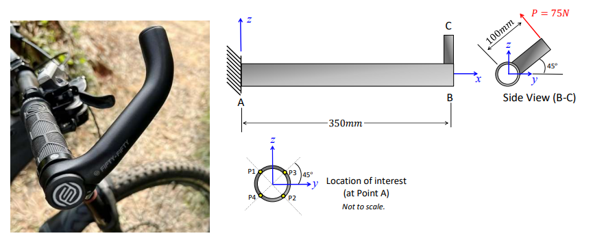
A mountain bike manufacturer is considering a new product line that will include handlebar
extenders applied to the ends of the handlebars, as shown below. To validate this design change,
you have been tasked with analysing the structure. You have produced an idealised structure, shown
below, where you consider half the length of the handlebars with a fixed boundary condition (A)
applied to the plane of symmetry. You have estimated that the maximum load that a rider can apply
to one handlebar extension is 75 Newtons that acts 100 mm from the centreline of the handlebars.
The handlebars have a circular cross-section with an outer diameter of 32 mm and a wall thickness
of 3.25 mm.To assess the design, you will:
state of stress at all points (P1, P2, P3 and P4) adjacent to the fixed support. These points are located on the exterior surface of the handlebars.
Present your results in a table and ensure that your sign convention is clearly shown (and
applied consistently!)

Step by step
Solved in 2 steps with 1 images
