Fig. Q3 shows an arrangement for controlling the temperature of a steam heated oven. utilizing temperature sensitive bellows and a hydraulic servomechanism. An increase in oven temperature causes the bellows to expand and the left end of the 'walking beam' ABC to move downwards. thus activating the hydraulic mechanism. The end C of the walking beam actuates a valve to reduce or increase the steam flow into the oven depending on the temperature in the oven. When .x is zero the beam ABC whose mid-point is B. is horizontal. Given that, (a) oil flow in the servomechanism per unit displacement (b) area of cross section of the piston in the working cylinder -Q - A (c) heat transfer across the walls of bellows to the thermos- sensitive fluid in the bellows q=H(0-7) where I' is the temperature of the fluid inside the bellows and H is a constant. (d) rate of change of temperature in the bellow's fluid Kq where K is a constant. (e) extension rate of the bellows per unit temperature rise in the fluid in the bellows FL Neglecting fluid compressibility, fluid leakage and inertia of moving parts draw a complete block diagram of the overall system and show that the transfer function relating the valve position y to L oven temperature can be expressed as (1+7₁8)(1+7₂8) Find expressions for 7₁ and 72.
Fig. Q3 shows an arrangement for controlling the temperature of a steam heated oven. utilizing temperature sensitive bellows and a hydraulic servomechanism. An increase in oven temperature causes the bellows to expand and the left end of the 'walking beam' ABC to move downwards. thus activating the hydraulic mechanism. The end C of the walking beam actuates a valve to reduce or increase the steam flow into the oven depending on the temperature in the oven. When .x is zero the beam ABC whose mid-point is B. is horizontal. Given that, (a) oil flow in the servomechanism per unit displacement (b) area of cross section of the piston in the working cylinder -Q - A (c) heat transfer across the walls of bellows to the thermos- sensitive fluid in the bellows q=H(0-7) where I' is the temperature of the fluid inside the bellows and H is a constant. (d) rate of change of temperature in the bellow's fluid Kq where K is a constant. (e) extension rate of the bellows per unit temperature rise in the fluid in the bellows FL Neglecting fluid compressibility, fluid leakage and inertia of moving parts draw a complete block diagram of the overall system and show that the transfer function relating the valve position y to L oven temperature can be expressed as (1+7₁8)(1+7₂8) Find expressions for 7₁ and 72.

Principles of Heat Transfer (Activate Learning with these NEW titles from Engineering!)
8th Edition
ISBN:9781305387102
Author:Kreith, Frank; Manglik, Raj M.
Publisher:Kreith, Frank; Manglik, Raj M.
Chapter6: Forced Convection Over Exterior Surfaces
Section: Chapter Questions
Problem 6.2DP

Related questions

Question
Transcribed Image Text:Oven
Temperature 0
wwwwww
Valve
↑y
Steam
B
Piston
Oil
Supply
H
Working
Cylinder
Fig. Q3
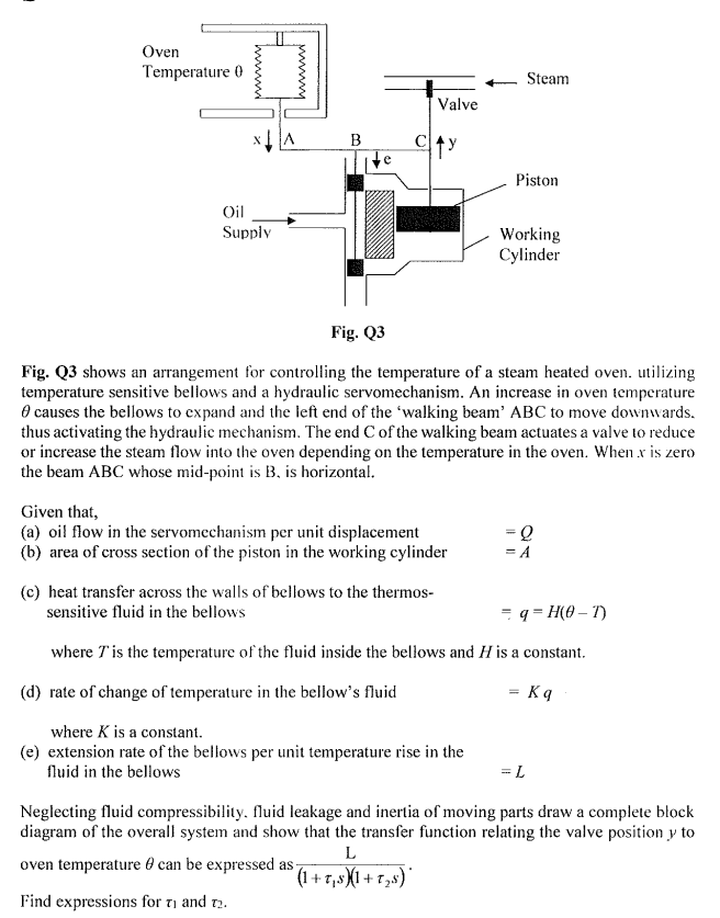
Fig. Q3 shows an arrangement for controlling the temperature of a steam heated oven. utilizing
temperature sensitive bellows and a hydraulic servomechanism. An increase in oven temperature
causes the bellows to expand and the left end of the 'walking beam' ABC to move downwards.
thus activating the hydraulic mechanism. The end C of the walking beam actuates a valve to reduce
or increase the steam flow into the oven depending on the temperature in the oven. When .x is zero
the beam ABC whose mid-point is B, is horizontal.
Given that,
(a) oil flow in the servomechanism per unit displacement
(b) area of cross section of the piston in the working cylinder
-Q
= A
(c) heat transfer across the walls of bellows to the thermos-
sensitive fluid in the bellows
=q=H(0-1)
where I' is the temperature of the fluid inside the bellows and H is a constant.
(d) rate of change of temperature in the bellow's fluid
Kq
where K is a constant.
(e) extension rate of the bellows per unit temperature rise in the
fluid in the bellows
= L
Neglecting fluid compressibility, fluid leakage and inertia of moving parts draw a complete block
diagram of the overall system and show that the transfer function relating the valve position y to
L
oven temperature can be expressed as-
(1+7₁8)(1+T₂s)
Find expressions for 71 and 72.
Expert Solution
This question has been solved!
Explore an expertly crafted, step-by-step solution for a thorough understanding of key concepts.

Step by step
Solved in 3 steps with 2 images

Knowledge Booster


Learn more about
Need a deep-dive on the concept behind this application? Look no further. Learn more about this topic, mechanical-engineering and related others by exploring similar questions and additional content below.Recommended textbooks for you
Principles of Heat Transfer (Activate Learning wi…
Mechanical Engineering
ISBN:
9781305387102
Author:
Kreith, Frank; Manglik, Raj M.
Publisher:
Cengage Learning

Refrigeration and Air Conditioning Technology (Mi…
Mechanical Engineering
ISBN:
9781305578296
Author:
John Tomczyk, Eugene Silberstein, Bill Whitman, Bill Johnson
Publisher:
Cengage Learning
Principles of Heat Transfer (Activate Learning wi…
Mechanical Engineering
ISBN:
9781305387102
Author:
Kreith, Frank; Manglik, Raj M.
Publisher:
Cengage Learning
Refrigeration and Air Conditioning Technology (Mi…
Mechanical Engineering
ISBN:
9781305578296
Author:
John Tomczyk, Eugene Silberstein, Bill Whitman, Bill Johnson
Publisher:
Cengage Learning