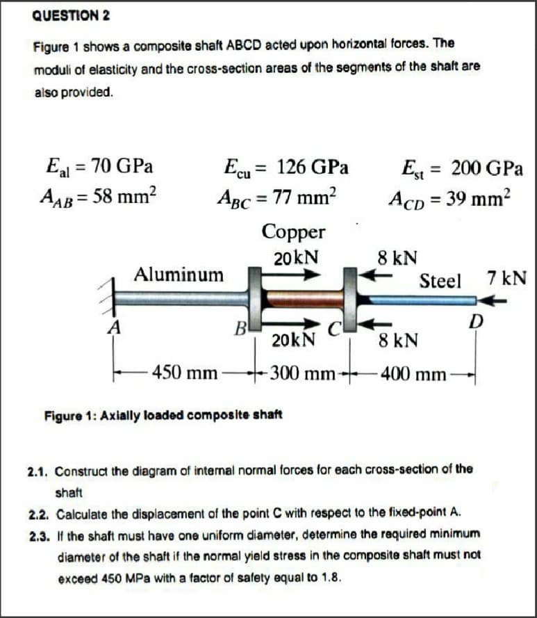
Figure 1 shows a composite shaft ABCD acted upon horizontal forces. The
Q: Q1: The shaft shown in Figure (1) is supported by two bearings and carries two V-belt sheaves.
A:
Q: Sketch the distribution of the shear stress due to torsion in a circular shaft. (simple sketch of…
A: Given : shear stress due to torsion in a circular shaft varies with shaft radius To find : Sketch…
Q: The end of a 2.5 in diameter steel shaft is milled to two flats (one flat on the top and one flat at…
A: Given data as per question Diameter of shaft =2.5 in Length of shaft =2 in Torque applied =750 lb.in…
Q: A circular shaft with 50mm and its lenght is 850mm long and is made of steel, the shaft is subjected…
A: GIVEN :- diameter : d=50mm length: L=850 mm Torque subjected: T=800Nm (to determine θ we need the…
Q: Compare the weights of equal lengths of hollow and solid shafts to transmit a given torque for the…
A:
Q: 4 mm module 20° full-depth The gear shown above is to transmit 1 kW at a speed of 200 rev/min. Find…
A:
Q: shaft along BC is twice as that of along AB. The torsional rigidity of AB is GJ. The torque required…
A: θAB=θBC [equal twist]TAB LG JAB =TBC LG JBC16* JAB = JBCTAB = TBC 16TAB +TBC = T17 TAB = TTAB…
Q: For your final design project, you use a keyway to hold your gear on the shaft. The radius of the…
A:
Q: The figure below shows the components of normal forces, the value of radial force on the gear wheel…
A: Write the given value using suitable variables. Here Ft signifies tangential force, and 0 signifies…
Q: 10. What is the minimum diameter in mm of a steel shaft which will be used to operate a 14 kN-m…
A:
Q: The input shaft to a gearbox, shown in Figure 3, operates at a speed of n1 and transmits a power of…
A:
Q: Figure below shows a shaft that is loaded as given, l at points B and D to allow the shaft to…
A: In the given problem, Reactions will be determined by treating the beam to be in equilibrium and…
Q: (7) The drive of an outboard motor which rotates @ 5,000rpm is supported by a spline in the…
A:
Q: A solid steel shaft is loaded as shown in Figure. U:
A: dear Student i have explained in detail . kindly refer the below solution
Q: What is the maximum shearing stress developed a solid steel shaft is subjected to a torque of 28…
A:
Q: The motor in the figure is transmits movement to the flywheel. The power of the engine is 4 kW and…
A:
Q: motor. The torque of the spindle is transferred to a wheat mill (not shown!) with the help of the…
A:
Q: A transmission shaft supporting a helical gear B and an overhung bevel gear D is shown in Fig. 400…
A:
Q: A hollow round steel shaft has a torque of 600 ft-lb. The shaft has an outside diameter of 1.25 in,…
A:
Q: Brass sleeve d: = 90mm di = 70mm Steel shaft B k= 200mm I- 200mm Figure 1: A compound of shaft…
A:
Q: For the steel shaft shown in Fig. Draw a torque diagram for the shaft. 80 ft-kip 40 ft-kip 25 ft-kip…
A: Given Data: The torque at point A is TA = -80 ft-kip. The torque at point B is TB = 100 ft-kip. The…
Q: A transmission shaft supporting a helical gear B and an overhung bevel gear D is shown in Fig.…
A:
Q: QUESTION 2 A shaft rotates at 300 rpm. 1), If it carries a spur gear that delivers 5 hp to a mating…
A: Given: N=300 rpm
Q: For the steel shaft shown in Fig. Draw a torque diagram for the shaft. 10 ft-kip 15 ft-kip 20 ft-kip…
A: given data as per the question Torque at point A =10 kip.ft Torque at point B =15 kip.ft Torque at…
Q: A steel shaft is transmitting 55 hp at 1200 rpm. The nature of the load and the type of service of…
A:
Q: A 52-kip-in. torque T is applied to the 3-in.-diameter solid aluminum shaft shown
A:
Q: If diameter of solid shaft is halved and torque being transmitted is doubled, what will be change in…
A: Shear stress (τ) in the shaft of diameter (d) due to torque (T) can be given by, τ = 16Tπ d3…
Q: Question.01 Figure TQ3.1 shows two shafts, A and B, arrange in parallel line are geared together…
A: Given DataMA=3mm=MCMD=MB=4.5mmZA=ZD=30
Q: A 3T Diameteð O is 93 mm Diametex ® is 53 mm G, 4니 GPa %3D 610 mm 321 mm Giz 75 GPa twist c/A = 0-27…
A:
Q: 3. Two shafts 30 in. apart, each carrying a four-step pulley, are to be connected by an open belt.…
A: In the above question the RPM of the driving shaft is given to be 150RPM and let us denote the…
Q: For the steel shaft shown in Fig. Draw a torque diagram for the shaft. 8 kN-m 15 kN-m 6 kN-m GGGGG T…
A: To determine: Torque diagram First, we have to calculate unknown torques. For this figure, TB is…
Q: Determine the maximum resultant bending moment for the input shaft (a) as shown in Figure . The…
A: Gear Gear is rotating circular part having cut teeth. Cut tooth are used to mesh with other gear and…
Q: The shaft shown in Figure 4 is loaded with concentrated torques at B, C, and D, and is fixed at A.…
A:
Q: Question 3 A shaft ABCD is shown in Figure 3 with total length, L = 2.1 m. The shaft BC is hollow…
A: Given that ,
Q: A 1.5 in diameter 10-spline shaft and permanent fit has a compressive force of 2000 lbs. Find the…
A: Write the formula for internal diameter of the 10-spline shaft. d=0.91D Here, D is the outer…
Q: a) Find the diameter of both shafts. b) If the modulus of rigidity of shaft (2) G is 77.2 GPa,…
A: for solution refer below images.
Q: 20 in. 40 in. 20 in. Figure shows a homogeneous body. 20° a. Draw the FBD 2400 lb-in. 30 in.…
A:
Q: PART B-ANALYSIS OF THE RESULTS 1- Using the following graph (with labelled axes) plot the…
A: For the different values of applied torque(T), diameter(D), and length(L) the angle of twist is…
Q: Use the following shaft layout assuming a pulley transmits torque through a key and keyseat at…
A:
Q: Ixoxd 150 pints a and b of the cantilever shafts show in the figure 10 KN 2. 200
A: Given: Transverse load on the beam: →P=10 KN=10000 N Length of the shaft→L=200 mm=0.2 m Outer…
Q: re are 8 screws on the pitch diameter C er d = 50 mm and transfers the power he hollow shaft is dex…
A:
Q: A 6-spline shaft and to slide when not under load has a diameter of 2.5 inches, if shearing force is…
A: given data; ⇒diameter (d)=2.5inch=63.5mm⇒shearing force (Fs)=2450lbs=10.90KN⇒hub length…
Q: rod is G. The expression for d to produce an angular twist 0 at the free end is
A: Given data; As shown in fig, Torque T is applied at the free end of a stepped rod of circular…
Q: 40 lb/in. 9 in. FIGURE PS-39 1. Compute the reactions at the supports using the tech- niques shown…
A:
Q: -100 Taper 1 in 100 What is kind of shaft coupling illustrated in Figure (1), Draw tow views…
A:
Q: For the steel shaft shown in Fig. Draw a torque diagram for the shaft. 30 kN-m 15 kN-m 5 kN-m B. 10…
A: Torque is the twisting moment applied at any point. To show the Torque variation along the shaft,…
Q: Quiz 2: The forces acting on gear-shaft-bearing system are shown in the figure given below. a)…
A:
Q: For the steel shaft shown in Fig. Draw a torque diagram for the shaft. 17 ft kip 60 ft-kip 12 ft-kip…
A: In this problem, the clock-wise torque is taken as positive and vice-versa. Write the expression of…
Will you kindly answer this question.
Step by step
Solved in 3 steps with 3 images
- Torsional T is applied to the hollow axis (G=80 GPa). Ewha Womans University, the maximum shear strain is γmax = 640 × 10-6rad Igo, inside andThe outside diameters are 120mm and 150mm, respectively.a. What is the maximum axial strain?b. Maximum axial stress?c. What is the maximum torque (T) meeting the above conditions?K=17 so 107 MPa strength of material question.If the shear modulus of a material is 120GPa & the bulk modulus is 140 GPa, then Young’s modulus is------ a. 820 GPa b. 280 Pa c. 280 GPa d. 820 Pa
- – The weight is suspended from structural A–36 steel alloy and 2014-T6 aluminum alloy wires, eachhaving the same initial length of 10 ft and cross-sectional area of 7×10⁻³ in2 (Figure Q1). If the weight is increasedgradually, determine which wire yields first? Explain which material model and yield criterion you will use? Justifyyour choicesPlease answer the problem completely. Provide a free body diagram. Final answer: • Pac = 8.84 kN (Compression) • Normal Stress = 8.84 kN (Compression)Find the amount of depression in mm at the midpoint of the bar AB. Mo= 1kNm, L = 1m, E = 200 GPa, I=1x106mm4
- BD rod made of G1 = 78 GPa with a diameter of 27 mm attached to the CA tube at point B, the tube made of G2 = 133 GPa had an outer diameter of 59 mm and a wall thickness of 10 mm. If T1 = 935 Nm and T2 = 1683 Nm, answer the following questions: 1- It is the polar inertial moment of the bar BD. 2- Maximum shear stress BD. 3- It is the polar moment of inertia of the CA tube. 4- It is the maximum shear stress BD. 5- It is the maximum shear stress of the CA tube. 6- It is the maximum shear stress of the assembly. 7- is the torsion angle between D and B. 8- It is the torsion angle between C and A. -9 is the torsion angle at D. 10- is the torsion angle between C and B. 11- is the reaction at point A.The cross sectional area of the bar is 5cm^2. Use E = 70GPa for aluminum, and E = 200 GPa for steel What is the elongation in segment AB (Aluminum)? a. 7.8571 x10^-3 m b. 6.8571 x10^-3 m c. -7.8571 x10^-3 m d. -6.8571 x10^-3 m What is the elongation in segment BC (Steel)? a. -3x10^-3 m b. 3x10^-3 m c. 2 x10^-3 m d. -2 x10^-3 m What is the elongation in segment CD (Aluminum)? a. -6.8571 x10^-3 m b. 6.8571 x10^-3 m c. -2.8571 x10^-3 m d. 2.8571 x10^-3 m What is the total elongation of the bar? a. 5 x10^-3 m b. 6 x10^-3 m c. 4 x10^-3 m d. -6 x10^-3 m -Draw and label the diagram correctly, No diagram in the solution will be marked wrong. -Shortcut solution will be marked wrong.- Direction of the assumption of the equilibrium equation must be shown, no direction will be marked wrong.Find the amount of depression in mm at the midpoint of the bar AB.Mo = 1kNm, L = 1m, E = 200 GPa, I=1x106 mm4
- Find the amount of slump at the midpoint of the bar AB, in mm. Mo= 1kNm, L = 1m, E = 200 GPa, I=1x106mm4(6) A key is to be designed for a 12.7cm shaft which will transmit power of 150kW @ 360 rpm. If the allowable compressive stress is 1,200kg/cm2, determine: (a) cross-sectional dimensions of the square key to be used; (b) length of the key.mechanics of rigid bodies The shaft assembly is made from a steel tube 1 in. in diameter, which is bonded to a solid brass core 0.5 in. in diameter. If a torque of 250 lb-ft is applied at its end, determine the maximum shear stress in psi experienced by the assembly. Take G for steel at 11.4x10³ ksi and G brass at 5.2 x 10³ ksi. with diagram if necessary.