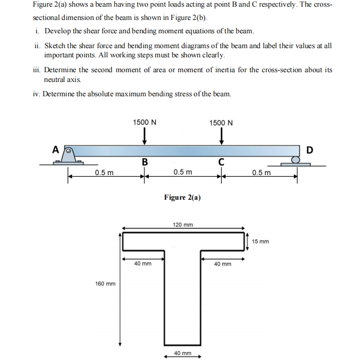
Figure 2(a) shows a beam having two point loads acting at point B and C respectively. The cross- sectional dimension of the beam is shown in Figure 2(b). i. Develop the shear force and bending moment equations of the beam. ii. Sketch the shear force and bending moment diagrams of the beam and label their values at all important points. All working steps must be shown clearly. iii. Determine the second moment of area or moment of inertia for the cross-section about its neutral axis. iv. Determine the absolute maximum bending stress of the beam. A 0.5 m 160 mm 1500 N ↓ B 40 mm 0.5 m Figure 2(a) 120 mm 40 mm 1500 N ↓ C 40 mm 0.5 m 15 mm D
Figure 2(a) shows a beam having two point loads acting at point B and C respectively. The cross- sectional dimension of the beam is shown in Figure 2(b). i. Develop the shear force and bending moment equations of the beam. ii. Sketch the shear force and bending moment diagrams of the beam and label their values at all important points. All working steps must be shown clearly. iii. Determine the second moment of area or moment of inertia for the cross-section about its neutral axis. iv. Determine the absolute maximum bending stress of the beam. A 0.5 m 160 mm 1500 N ↓ B 40 mm 0.5 m Figure 2(a) 120 mm 40 mm 1500 N ↓ C 40 mm 0.5 m 15 mm D

Mechanics of Materials (MindTap Course List)
9th Edition
ISBN:9781337093347
Author:Barry J. Goodno, James M. Gere
Publisher:Barry J. Goodno, James M. Gere
Chapter10: Statically Indeterminate Beams
Section: Chapter Questions
Problem 10.3.13P: A counterclockwise moment M0acts at the midpoint of a fixed-end beam ACB of length L (see figure)....

Related questions

Question
Transcribed Image Text:Figure 2(a) shows a beam having two point loads acting at point B and C respectively. The cross-
sectional dimension of the beam is shown in Figure 2 (b).
i. Develop the shear force and bending moment equations of the beam.
ii. Sketch the shear force and bending moment diagrams of the beam and label their values at all
important points. All working steps must be shown clearly.
iii. Determine the second moment of area or moment of inertia for the cross-section about its
neutral axis.
iv. Determine the absolute maximum bending stress of the beam.
A
0.5 m
160 mm
1500 N
↓
B
40 mm
0.5 m
Figure 2(a)
120 mm
40 mm
1500 N
↓
C
40 mm
0.5 m
15 mm
D
Expert Solution
This question has been solved!
Explore an expertly crafted, step-by-step solution for a thorough understanding of key concepts.

This is a popular solution!

Trending now
This is a popular solution!

Step by step
Solved in 2 steps with 2 images

Knowledge Booster


Learn more about
Need a deep-dive on the concept behind this application? Look no further. Learn more about this topic, mechanical-engineering and related others by exploring similar questions and additional content below.Recommended textbooks for you
Mechanics of Materials (MindTap Course List)
Mechanical Engineering
ISBN:
9781337093347
Author:
Barry J. Goodno, James M. Gere
Publisher:
Cengage Learning
Mechanics of Materials (MindTap Course List)
Mechanical Engineering
ISBN:
9781337093347
Author:
Barry J. Goodno, James M. Gere
Publisher:
Cengage Learning