Figure 6 shows a circuit where feedback is provided between the drain and gate of the transistor M1 (a) Draw the small signal equivalent circuit of the open loop circuit obtained by breaking the loop at the gate of transistor M1 (suitable for the analysis in the mid band frequency range). Consider Cg as short circuit in the model and state any assumption. (b) State the necessary conditions for the oscillation to occur in the circuit. (c) Using the conditions from (b), derive an expression for the amplifier oscillation frequency fo. Derive the necessary condition for the oscillation to occur in the circuit and state if you can conclude that the circuit will oscillate when considering the values of the inductances L2 = 8 L1 transconductance of the transistor gml = (d) 2 mH; capacitors C = 2 nF; 1.4 mS; and resistors R1 = R2 = Rs = %3D %3D 10 k2. R1 Vout Cp HC M1 R2 CG Rs Cs V ss = 0 V Figure 6
Figure 6 shows a circuit where feedback is provided between the drain and gate of the transistor M1 (a) Draw the small signal equivalent circuit of the open loop circuit obtained by breaking the loop at the gate of transistor M1 (suitable for the analysis in the mid band frequency range). Consider Cg as short circuit in the model and state any assumption. (b) State the necessary conditions for the oscillation to occur in the circuit. (c) Using the conditions from (b), derive an expression for the amplifier oscillation frequency fo. Derive the necessary condition for the oscillation to occur in the circuit and state if you can conclude that the circuit will oscillate when considering the values of the inductances L2 = 8 L1 transconductance of the transistor gml = (d) 2 mH; capacitors C = 2 nF; 1.4 mS; and resistors R1 = R2 = Rs = %3D %3D 10 k2. R1 Vout Cp HC M1 R2 CG Rs Cs V ss = 0 V Figure 6

Power System Analysis and Design (MindTap Course List)
6th Edition
ISBN:9781305632134
Author:J. Duncan Glover, Thomas Overbye, Mulukutla S. Sarma
Publisher:J. Duncan Glover, Thomas Overbye, Mulukutla S. Sarma
Chapter12: Power System Controls
Section: Chapter Questions
Problem 12.3P

Related questions
Question
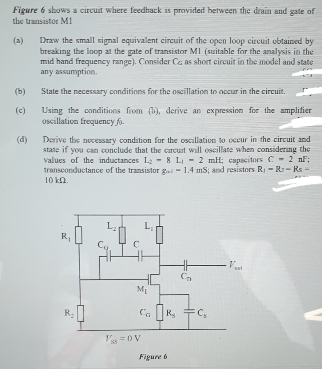
Transcribed Image Text:Figure 6 shows a circuit where feedback is provided between the drain and gate of
the transistor M1
Draw the small signal equivalent circuit of the open loop circuit obtained by
breaking the loop at the gate of transistor M1 (suitable for the analysis in the
mid band frequency range). Consider Cg as short circuit in the model and state
any assumption.
(a)
(b)
State the necessary conditions for the oscillation to occur in the circuit.
Using the conditions from (b), derive an expression for the amplifier
oscillation frequency fo.
(c)
Derive the necessary condition for the oscillation to occur in the circuit and
state if you can conclude that the circuit will oscillate when considering the
values of the inductances L2 = 8 Li = 2 mH; capacitors C = 2 nF;
transconductance of the transistor gmi = 1.4 mS; and resistors R1 = R2= Rs =
10 k2.
(d)
%3D
%3D
L2
R1
C
V out
Cp
M1
R2
CG
Rs
Cs
Vss =0 V
Figure 6
Expert Solution
This question has been solved!
Explore an expertly crafted, step-by-step solution for a thorough understanding of key concepts.

Step by step
Solved in 2 steps with 2 images

Knowledge Booster


Learn more about
Need a deep-dive on the concept behind this application? Look no further. Learn more about this topic, electrical-engineering and related others by exploring similar questions and additional content below.Recommended textbooks for you
Power System Analysis and Design (MindTap Course …
Electrical Engineering
ISBN:
9781305632134
Author:
J. Duncan Glover, Thomas Overbye, Mulukutla S. Sarma
Publisher:
Cengage Learning
Power System Analysis and Design (MindTap Course …
Electrical Engineering
ISBN:
9781305632134
Author:
J. Duncan Glover, Thomas Overbye, Mulukutla S. Sarma
Publisher:
Cengage Learning