Figure < 1 of 1 -1.75 m- -2.50 m- F E 30 B. M 30 0.5 m 0.65 m

International Edition---engineering Mechanics: Statics, 4th Edition
4th Edition
ISBN:9781305501607
Author:Andrew Pytel And Jaan Kiusalaas
Publisher:Andrew Pytel And Jaan Kiusalaas
Chapter6: Beams And Cables
Section: Chapter Questions
Problem 6.76P: The 50-ft measuring tape weighs 2.4 lb. Compute the span L of the tape to four significant figures.

Related questions

Question
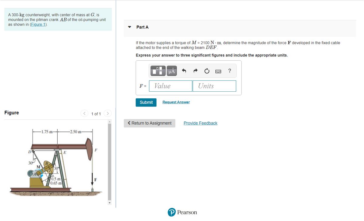
Transcribed Image Text:A 300-kg counterweight, with center of mass at G, is
mounted on the pitman crank AB of the oil-pumping unit
as shown in (Figure 1).
Part A
If the motor supplies a torque of M = 2100 N · m, determine the magnitude of the force F developed in the fixed cable
attached to the end of the walking beam DEF.
Express your answer to three significant figures and include the appropriate units.
μΑ
?
F =
Value
Units
Submit
Request Answer
Figure
1 of 1
< Return to Assignment
Provide Feedback
1.75 m-
-2.50 m-
D
30
30
0.5 m
0.65 m
P Pearson
Expert Solution
This question has been solved!
Explore an expertly crafted, step-by-step solution for a thorough understanding of key concepts.

Step by step
Solved in 3 steps with 2 images

Knowledge Booster


Learn more about
Need a deep-dive on the concept behind this application? Look no further. Learn more about this topic, mechanical-engineering and related others by exploring similar questions and additional content below.Recommended textbooks for you
International Edition---engineering Mechanics: St…
Mechanical Engineering
ISBN:
9781305501607
Author:
Andrew Pytel And Jaan Kiusalaas
Publisher:
CENGAGE L
International Edition---engineering Mechanics: St…
Mechanical Engineering
ISBN:
9781305501607
Author:
Andrew Pytel And Jaan Kiusalaas
Publisher:
CENGAGE L