Determine the maximum shear force in kN in the figure below. 2 kN/m B A C 5 kN 4 m 2 m O -10 O 10 O -5 O 5
Determine the maximum shear force in kN in the figure below. 2 kN/m B A C 5 kN 4 m 2 m O -10 O 10 O -5 O 5

Mechanics of Materials (MindTap Course List)
9th Edition
ISBN:9781337093347
Author:Barry J. Goodno, James M. Gere
Publisher:Barry J. Goodno, James M. Gere
Chapter5: Stresses In Beams (basic Topics)
Section: Chapter Questions
Problem 5.8.1P: The shear stresses t in a rectangular beam arc given by Eq. (5-43): in which Fis the shear force, /...

Related questions
Question
Transcribed Image Text:Question 62
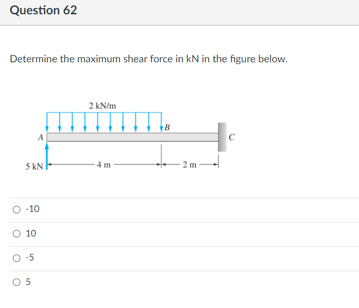
Determine the maximum shear force in kN in the figure below.
2 kN/m
А
5 kN
4 m
2 m
-10
O 10
O-5
O 5
Expert Solution
This question has been solved!
Explore an expertly crafted, step-by-step solution for a thorough understanding of key concepts.

Step by step
Solved in 2 steps with 2 images

Knowledge Booster


Learn more about
Need a deep-dive on the concept behind this application? Look no further. Learn more about this topic, mechanical-engineering and related others by exploring similar questions and additional content below.Recommended textbooks for you
Mechanics of Materials (MindTap Course List)
Mechanical Engineering
ISBN:
9781337093347
Author:
Barry J. Goodno, James M. Gere
Publisher:
Cengage Learning
Mechanics of Materials (MindTap Course List)
Mechanical Engineering
ISBN:
9781337093347
Author:
Barry J. Goodno, James M. Gere
Publisher:
Cengage Learning