Figure Q3(a) shows an approximate and actual Bode Plot for magnitude and phase. From the given Bode Plot, extract all the information that you might think valuable to the user as a control engineer. You can choose either to use the approximate Bode Plot or actual Bode Plot in this analysis. Magnetude Plot 40 Appresimate -Actual 20 아. -80 Freg irads) Phase Plot Apprte -100 Actul -120 -140 i-160 -180 200 220 240 -280- Freg irad's) (P)pro
Figure Q3(a) shows an approximate and actual Bode Plot for magnitude and phase. From the given Bode Plot, extract all the information that you might think valuable to the user as a control engineer. You can choose either to use the approximate Bode Plot or actual Bode Plot in this analysis. Magnetude Plot 40 Appresimate -Actual 20 아. -80 Freg irads) Phase Plot Apprte -100 Actul -120 -140 i-160 -180 200 220 240 -280- Freg irad's) (P)pro

Delmar's Standard Textbook Of Electricity
7th Edition
ISBN:9781337900348
Author:Stephen L. Herman
Publisher:Stephen L. Herman
Chapter24: Resistive-inductive-capacitive Parallel Circuits
Section: Chapter Questions
Problem 4RQ: A tank circuit contains a capacitor and an inductor that produce 30 of reactance at the resonant...

Related questions
Question
Transcribed Image Text:QUESTION 3
(a)
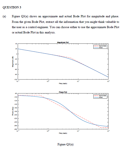
Figure Q3(a) shows an approximate and actual Bode Plot for magnitude and phase.
From the given Bode Plot, extract all the information that you might think valuable to
the user as a control engineer. You can choose either to use the approximate Bode Plot
or actual Bode Plot in this analysis.
Magnitude Plot
40
Approimate
-Actual
20
-80
-100
To
Freg rad's)
Phase Plot
Approainate
-100
Actual
-120
-140
6-160
E -200
-220 -
-240
-260
Freg radis)
Figure Q3(a)
Expert Solution
This question has been solved!
Explore an expertly crafted, step-by-step solution for a thorough understanding of key concepts.

Step by step
Solved in 3 steps

Knowledge Booster


Learn more about
Need a deep-dive on the concept behind this application? Look no further. Learn more about this topic, electrical-engineering and related others by exploring similar questions and additional content below.Recommended textbooks for you
Delmar's Standard Textbook Of Electricity
Electrical Engineering
ISBN:
9781337900348
Author:
Stephen L. Herman
Publisher:
Cengage Learning
Delmar's Standard Textbook Of Electricity
Electrical Engineering
ISBN:
9781337900348
Author:
Stephen L. Herman
Publisher:
Cengage Learning