Find: 1. Voltage at the source (no capacitors are installed) 2. Capacitors are installed at the load so that the power factor of the load is improved to 0.95. What would be the voltage at the source in this case? 3. How much money could be saved in loss reduction in the transmission line annually due to the installation of capacitors if the Load Factor (LdF) = 0.7, there are 8760 hours in a year, and energy cost is $0.007/KwHr? (See comments below).
Find: 1. Voltage at the source (no capacitors are installed) 2. Capacitors are installed at the load so that the power factor of the load is improved to 0.95. What would be the voltage at the source in this case? 3. How much money could be saved in loss reduction in the transmission line annually due to the installation of capacitors if the Load Factor (LdF) = 0.7, there are 8760 hours in a year, and energy cost is $0.007/KwHr? (See comments below).

Power System Analysis and Design (MindTap Course List)
6th Edition
ISBN:9781305632134
Author:J. Duncan Glover, Thomas Overbye, Mulukutla S. Sarma
Publisher:J. Duncan Glover, Thomas Overbye, Mulukutla S. Sarma
Chapter4: Transmission Line Parameters
Section: Chapter Questions
Problem 4.23P

Related questions
Question
Transcribed Image Text:Find:
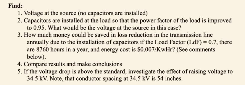
1. Voltage at the source (no capacitors are installed)
2. Capacitors are installed at the load so that the power factor of the load is improved
to 0.95. What would be the voltage at the source in this case?
3. How much money could be saved in loss reduction in the transmission line
annually due to the installation of capacitors if the Load Factor (LdF) = 0.7, there
are 8760 hours in a year, and energy cost is $0.007/KwHr? (See comments
below).
4. Compare results and make conclusions
5. If the voltage drop is above the standard, investigate the effect of raising voltage to
34.5 kV. Note, that conductor spacing at 34.5 kV is 54 inches.
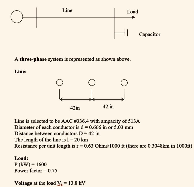
Transcribed Image Text:Line
Load
Capacitor
A three-phase system is represented as shown above.
Line:
42in
42 in
Line is selected to be AAC #336.4 with ampacity of 513A
Diameter of each conductor is d = 0.666 in or 5.03 mm
Distance between conductors D= 42 in
The length of the line is 1 = 20 km
Resistance per unit length is r= 0.63 Ohms/1000 ft (there are 0.3048km in 1000ft)
Load:
P (kW) = 1600
Power factor = 0.75
Voltage at the load V = 13.8 kV
Expert Solution
This question has been solved!
Explore an expertly crafted, step-by-step solution for a thorough understanding of key concepts.

Step by step
Solved in 5 steps with 1 images

Recommended textbooks for you
Power System Analysis and Design (MindTap Course …
Electrical Engineering
ISBN:
9781305632134
Author:
J. Duncan Glover, Thomas Overbye, Mulukutla S. Sarma
Publisher:
Cengage Learning

EBK ELECTRICAL WIRING RESIDENTIAL
Electrical Engineering
ISBN:
9781337516549
Author:
Simmons
Publisher:
CENGAGE LEARNING - CONSIGNMENT
Power System Analysis and Design (MindTap Course …
Electrical Engineering
ISBN:
9781305632134
Author:
J. Duncan Glover, Thomas Overbye, Mulukutla S. Sarma
Publisher:
Cengage Learning
EBK ELECTRICAL WIRING RESIDENTIAL
Electrical Engineering
ISBN:
9781337516549
Author:
Simmons
Publisher:
CENGAGE LEARNING - CONSIGNMENT