Find an estimate for the lower and upper cut-off frequencies for the amplifier circuit shown in Figure Q4. Q4. The device capacitances for the transistors are: Chel = 30 pF, Chel = 2 pF, Ceel = 0.1 pF, Che2 = 20 pF, Chc2 = 1 pF and Cee2 =0.25 pF. Use B = 100 for both transistors in your calculations. The small signal model parameters for the transistors are: Tal = 2 k2, gml = 50 mS, r2 =4 kN, gm2 = 25 mS, For the low-frequency: @ where Tps are the time constants for the capacitors. For the high-frequency: Vc 14 V Rs 5.6 kn 180 pF R 68 k R Q, 2N 3905 5.6 kn 2N Qi 3903 15 uF R2 68 k 0.47 uF 600n 220 n RL 40 ka R3 47 k R. 5.6 ksa 4.7 k2 Figure Q4
Find an estimate for the lower and upper cut-off frequencies for the amplifier circuit shown in Figure Q4. Q4. The device capacitances for the transistors are: Chel = 30 pF, Chel = 2 pF, Ceel = 0.1 pF, Che2 = 20 pF, Chc2 = 1 pF and Cee2 =0.25 pF. Use B = 100 for both transistors in your calculations. The small signal model parameters for the transistors are: Tal = 2 k2, gml = 50 mS, r2 =4 kN, gm2 = 25 mS, For the low-frequency: @ where Tps are the time constants for the capacitors. For the high-frequency: Vc 14 V Rs 5.6 kn 180 pF R 68 k R Q, 2N 3905 5.6 kn 2N Qi 3903 15 uF R2 68 k 0.47 uF 600n 220 n RL 40 ka R3 47 k R. 5.6 ksa 4.7 k2 Figure Q4

Introductory Circuit Analysis (13th Edition)
13th Edition
ISBN:9780133923605
Author:Robert L. Boylestad
Publisher:Robert L. Boylestad
Chapter1: Introduction
Section: Chapter Questions
Problem 1P: Visit your local library (at school or home) and describe the extent to which it provides literature...

Related questions

Question
Electrical Engineering - Electronic ll Please solve the question quickly
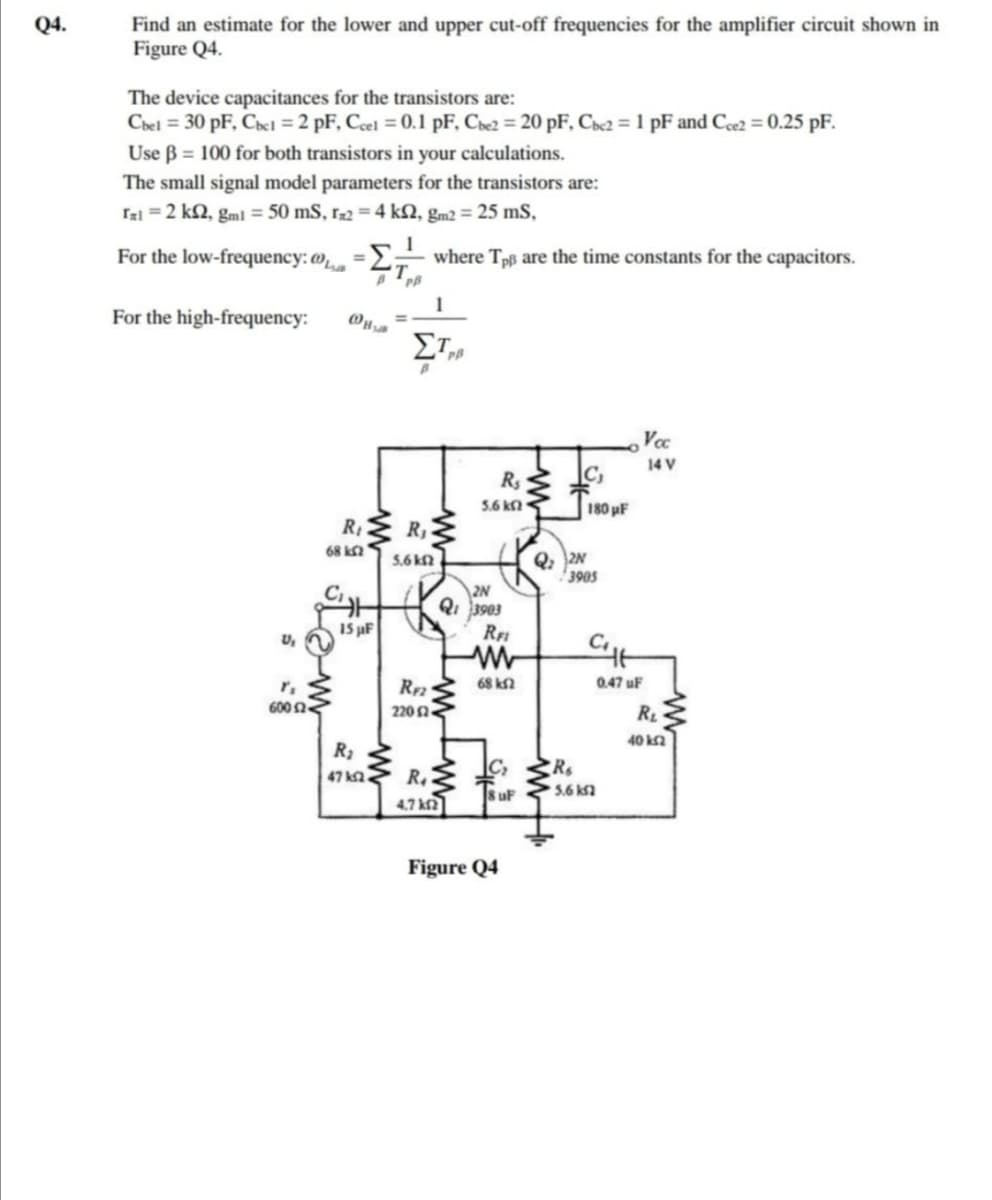
Transcribed Image Text:Q4.
Find an estimate for the lower and upper cut-off frequencies for the amplifier circuit shown in
Figure Q4.
The device capacitances for the transistors are:
Chel = 30 pF, Chel = 2 pF, Cel = 0.1 pF, Che2 = 20 pF, Che2 = 1 pF and Cee2 = 0.25 pF.
Use B = 100 for both transistors in your calculations.
The small signal model parameters for the transistors are:
Tal = 2 k2, gml = 50 mS, r-2 = 4 kN, gm2 = 25 mS,
%3D
For the low-frequency: @
where Tpß are the time constants for the capacitors.
For the high-frequency:
Vc
14 V
C,
Rs
5.6 kn
180 uF
R
R,
68 k
Q, 2N
3905
5.6 kN
|2N
Qi 3903
1S µF
R
U,
68 k2
0.47 uF
600 n
220 n
R
40 ka
R
47 ka
8 uF
5.6 ksa
4.7 ka
Figure Q4
Expert Solution
This question has been solved!
Explore an expertly crafted, step-by-step solution for a thorough understanding of key concepts.

Step by step
Solved in 3 steps

Knowledge Booster


Learn more about
Need a deep-dive on the concept behind this application? Look no further. Learn more about this topic, electrical-engineering and related others by exploring similar questions and additional content below.Recommended textbooks for you
Introductory Circuit Analysis (13th Edition)
Electrical Engineering
ISBN:
9780133923605
Author:
Robert L. Boylestad
Publisher:
PEARSON

Delmar's Standard Textbook Of Electricity
Electrical Engineering
ISBN:
9781337900348
Author:
Stephen L. Herman
Publisher:
Cengage Learning

Programmable Logic Controllers
Electrical Engineering
ISBN:
9780073373843
Author:
Frank D. Petruzella
Publisher:
McGraw-Hill Education
Introductory Circuit Analysis (13th Edition)
Electrical Engineering
ISBN:
9780133923605
Author:
Robert L. Boylestad
Publisher:
PEARSON
Delmar's Standard Textbook Of Electricity
Electrical Engineering
ISBN:
9781337900348
Author:
Stephen L. Herman
Publisher:
Cengage Learning
Programmable Logic Controllers
Electrical Engineering
ISBN:
9780073373843
Author:
Frank D. Petruzella
Publisher:
McGraw-Hill Education

Fundamentals of Electric Circuits
Electrical Engineering
ISBN:
9780078028229
Author:
Charles K Alexander, Matthew Sadiku
Publisher:
McGraw-Hill Education

Electric Circuits. (11th Edition)
Electrical Engineering
ISBN:
9780134746968
Author:
James W. Nilsson, Susan Riedel
Publisher:
PEARSON

Engineering Electromagnetics
Electrical Engineering
ISBN:
9780078028151
Author:
Hayt, William H. (william Hart), Jr, BUCK, John A.
Publisher:
Mcgraw-hill Education,