Find (Z) through A, with ro = 25kN and compare results. must using the hybrid (h - parameters) equivalent model 12 V R 220 k2 10 μ B = 100, r,= 2 10 μF RE 3.3 k2 FIG. 5.39 Example 5.7.
Find (Z) through A, with ro = 25kN and compare results. must using the hybrid (h - parameters) equivalent model 12 V R 220 k2 10 μ B = 100, r,= 2 10 μF RE 3.3 k2 FIG. 5.39 Example 5.7.

Delmar's Standard Textbook Of Electricity
7th Edition
ISBN:9781337900348
Author:Stephen L. Herman
Publisher:Stephen L. Herman
Chapter29: Dc Generators
Section: Chapter Questions
Problem 16RQ: Explain the difference between cumulative- and differential-compounded connections.

Related questions
Question
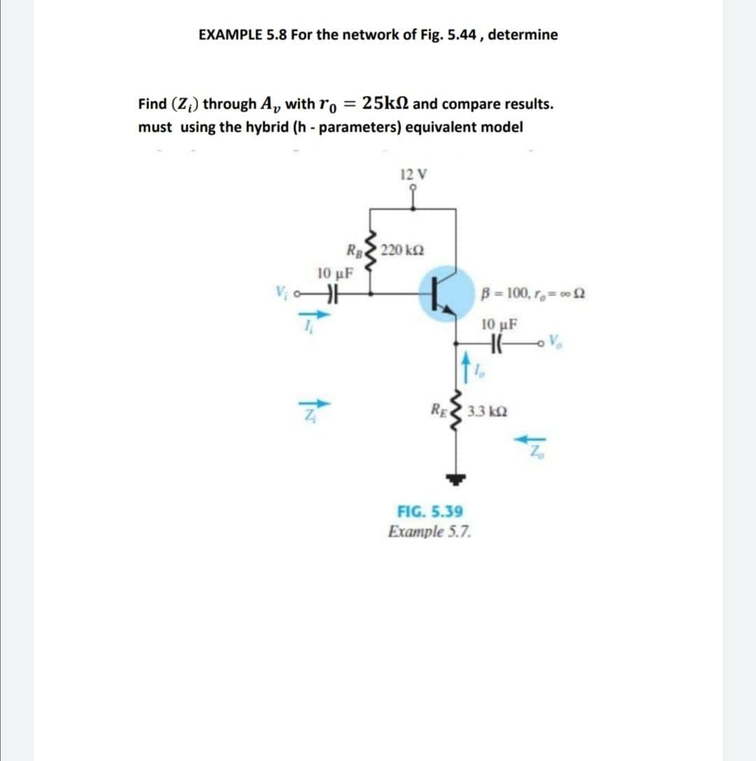
Transcribed Image Text:EXAMPLE 5.8 For the network of Fig. 5.44 , determine
Find (Z;) through A, with ro
25kN and compare results.
%3D
must using the hybrid (h - parameters) equivalent model
12 V
RE 220 k2
10 μF
B = 100, r,= 00 2
10 μF
RE
3.3 k2
FIG. 5.39
Example 5.7.
Expert Solution
This question has been solved!
Explore an expertly crafted, step-by-step solution for a thorough understanding of key concepts.

Step by step
Solved in 2 steps with 2 images

Knowledge Booster


Learn more about
Need a deep-dive on the concept behind this application? Look no further. Learn more about this topic, electrical-engineering and related others by exploring similar questions and additional content below.Recommended textbooks for you
Delmar's Standard Textbook Of Electricity
Electrical Engineering
ISBN:
9781337900348
Author:
Stephen L. Herman
Publisher:
Cengage Learning
Delmar's Standard Textbook Of Electricity
Electrical Engineering
ISBN:
9781337900348
Author:
Stephen L. Herman
Publisher:
Cengage Learning