First, you must create a logic circuit using only basic gates such as AND, OR, NOR, NAND, NOT, etc. to implement an ADDER capable of adding two 4 bit binary numbers. Second, you must create a logic circuit using only basic gates such as AND, OR, NOR, NAND, NOT, etc. to implement a Subtractor that is capable of subtracting the second number from the first, by converting the second number into its 2's complement form and then adding the resulting number to the first number. You do not need to worry about accomodating the addition or subtraction of negative numbers. Finally, create a limited ALU (Arithmetic logic unit) circuit using Logism that implements a Full Adder circuit capable of adding 2 – 4 bit binary numbers and subtracting 2- 4 bit binary numbers. Also, implement the ability to select a bitwise AND operation and a bitwise OR operation. For the ALU it is acceptable to use the Adder and Subtractor circuits that are listed under the "Arithmetic" folder in Logism. (Logism tips and tricks are useful here for multi-bit pins, and how to set up different gates to support more than 1 bit. If using YOUR adder or subtractor circuit in your ALU that is not only acceptable but would be preferred (it is not required as it will make the circuit much more complex) in order to do this you should learn to make use of the splitter that is located in the "Wiring" folder in Logism as this can simpify wiring all of the functions together. This demonstrates many of the key elements that are required for an operational ALU (Arithmetic Logic Unit). First of all, we are providing two inputs or operands which will be used in a computation. We are implementing four of the most important computations including add, subtract, bitwise AND, and bitwise OR. Obviously, this would not be a complete ALU, but it does provide us with an understanding of the operation of the ALU and gives us some experience with designing components of the ALU. Your circuit should use a multiplexor that will select between the add, subtract, AND, and OR operations. The multiplexor will select the operations using 2 bits for the selection as follows: 0 0 - Add 0 1 - Subtract 1 0 - AND 1 1 - OR What this means is that when the selection bits on the multiplexor (or demultiplexor as the case may be) are set it enables the path from one of the functions Add, Subtract, AND, and OR. Your subtract circuit must convert the second of your two input numbers into 2’s complement format and then add the resulting binary number to the first number as this will effectively subtract the second binary number from the first binary number. Remember to convert a number into 2's complement requires two steps. First, the bits of the number must be inverted (make all 1's into 0's and make all 0's into 1's) second add one to this inverted number. You could use a circuit similar to the following for this. DO NOT use the examples that I have provided here. They are meant to be illustrative but are NOT necessarily complete. Your circuit should look similar to the following diagram (again this is meant to be illustrative it is NOT complete) with the two binary numbers to be added on the left, a bit selector that will select the operation to be performed. When it is 0 the adder circuit should be selected and when 1 the subtraction circuit should be selected. Of the output of the computation should be on the right. Your circuit should follow this basic format, but you must design all of the actual circuits to perform addition and subtraction. You must design the actual connections between components what I have represented below is just to give an idea of where you should put the inputs, outputs, and processing that occurs in between.


First, you must create a logic circuit using only basic gates such as AND, OR, NOR, NAND, NOT, etc. to implement an ADDER capable of adding two 4 bit binary numbers.
Second, you must create a logic circuit using only basic gates such as AND, OR, NOR, NAND, NOT, etc. to implement a Subtractor that is capable of subtracting the second number from the first, by converting the second number into its 2's complement form and then adding the resulting number to the first number. You do not need to worry about accomodating the addition or subtraction of negative numbers.
Finally, create a limited ALU (Arithmetic logic unit) circuit using Logism that implements a Full Adder circuit capable of adding 2 – 4 bit binary numbers and subtracting 2- 4 bit binary numbers. Also, implement the ability to select a bitwise AND operation and a bitwise OR operation. For the ALU it is acceptable to use the Adder and Subtractor circuits that are listed under the "Arithmetic" folder in Logism. (Logism tips and tricks are useful here for multi-bit pins, and how to set up different gates to support more than 1 bit.
If using YOUR adder or subtractor circuit in your ALU that is not only acceptable but would be preferred (it is not required as it will make the circuit much more complex) in order to do this you should learn to make use of the splitter that is located in the "Wiring" folder in Logism as this can simpify wiring all of the functions together.
This demonstrates many of the key elements that are required for an operational ALU (Arithmetic Logic Unit). First of all, we are providing two inputs or operands which will be used in a computation. We are implementing four of the most important computations including add, subtract, bitwise AND, and bitwise OR. Obviously, this would not be a complete ALU, but it does provide us with an understanding of the operation of the ALU and gives us some experience with designing components of the ALU.
Your circuit should use a multiplexor that will select between the add, subtract, AND, and OR operations. The multiplexor will select the operations using 2 bits for the selection as follows:
0 0 - Add
0 1 - Subtract
1 0 - AND
1 1 - OR
What this means is that when the selection bits on the multiplexor (or demultiplexor as the case may be) are set it enables the path from one of the functions Add, Subtract, AND, and OR.
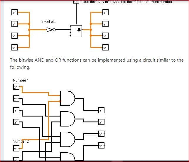
Your subtract circuit must convert the second of your two input numbers into 2’s complement format and then add the resulting binary number to the first number as this will effectively subtract the second binary number from the first binary number. Remember to convert a number into 2's complement requires two steps. First, the bits of the number must be inverted (make all 1's into 0's and make all 0's into 1's) second add one to this inverted number. You could use a circuit similar to the following for this.
DO NOT use the examples that I have provided here. They are meant to be illustrative but are NOT necessarily complete.
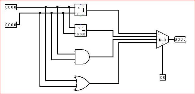
Your circuit should look similar to the following diagram (again this is meant to be illustrative it is NOT complete) with the two binary numbers to be added on the left, a bit selector that will select the operation to be performed. When it is 0 the adder circuit should be selected and when 1 the subtraction circuit should be selected. Of the output of the computation should be on the right.
Your circuit should follow this basic format, but you must design all of the actual circuits to perform addition and subtraction. You must design the actual connections between components what I have represented below is just to give an idea of where you should put the inputs, outputs, and processing that occurs in between.


Trending now
This is a popular solution!

Step by step
Solved in 2 steps with 1 images


