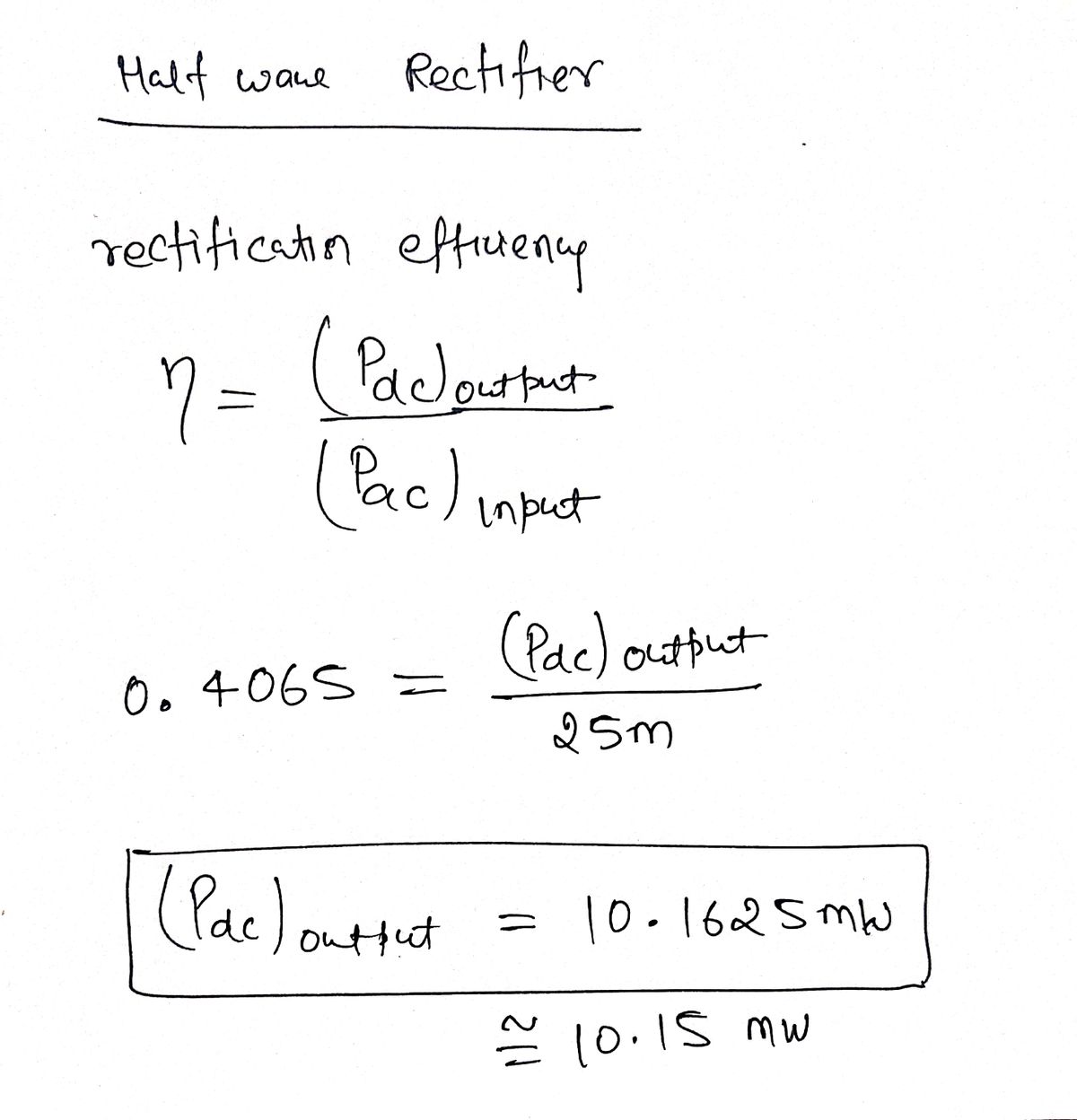
For a half wave rectifier with efficiency (N) 40.65 % and input ac power 25mW.Compute the output dc power across the load 3k0. O a. 10.15W O b. 1.015kW O c. 1.015mW d. 10.15mW


Q: A full-wave bridge rectifier with a 236.86V p-p sinusoidal input has a load resister of2KΩ i. Draw…
A: “Since you have posted a question with multiple sub-parts, we will solve the first three subparts…
Q: Consider a peak rectifier fed by a 60-Hz sinusoid having a peak value Vp = 100 V. Let load…
A: Given:Frequency,f=60HzVP=100VR=10KΩVR p-p=2V
Q: e) Explain the internal structure of a 60 pulse rectifier. How many full-wave three- phase…
A: Since we are allowed to solve only up to three sub parts of a question the answer below contains…
Q: Determine the peak output voltage for the bridge rectifier. Assuming ideal model, what PIV rating is…
A: The solution is given below
Q: a. Draw a circuit diagram for a full wave rectifier with a capacitor filter. What does the charging…
A: Full wave Rectifier, Circuit diagram of the full wave rectifier with capacitor filter. How to…
Q: A voltmeter measures an AC voltage of 150 V. a) What is the peak voltage? What is the RMS voltage?…
A: Given voltmeter measures an AC voltage of 150 V
Q: In the single-phase diode rectifier circuit shown in Figure 1 and a constant dc load current Ia =…
A: To determine the various parameters in the given single-phase diode bridge rectifier. Given: id =…
Q: The full-wave rectifier ias shown is operating at a frequency of 60 Hz, and the rms value of the…
A: We are authorized to answer three subparts at a time since you have not mentioned which part you are…
Q: In the single-phase diode rectifier circuit shown in Figure 1 and a constant dc load current la=…
A: The given details are :-Vs=120 V RHS supply voltagef= 60 HZId= 10 A Average output currenti) The…
Q: 3. For the half-wave rectifier given in the figure below, find the average values of the output…
A:
Q: 28. A full-wave bridge rectifier with a 120-V rms sinusoidal input has a load resistor of 1 kN. a.…
A: Since you have asked multiple questions in a single request, we will be answering only the first…
Q: Write the following for a Semiconverter rectifier with RL load: a) Draw the circuit diagram, supply…
A: There are many devices that work with DC supply, but the supply present is naturally AC. The…
Q: 2. A full-wave bridge type rectifier with a 120 Vrms sinusoidal input has a load resistor of 1 kN.…
A: We need to find dc voltage and PIV .
Q: Derive the expression for average or dc voltage Vdc for a full-wave rectifier using time variable.
A:
Q: If a diode full wave rectifier circuit is excited by an ac source with an amplitude of 10 V and…
A: For a full wave rectifier circuit using diodes, if VP is the amplitude of the ac signal voltage…
Q: Matter Energy Transformation, answer the following questions: It is very necessary Answer the…
A: In this question , we will find expression for average voltage and RMS voltage of half wave…
Q: Q4. In the full-wave diode rectifier shown below, the diodes are ideal. The source voltage is v, =…
A:
Q: 2. What is the value of the peak inverse voltage on the diode in full-wave rectifier? 3. Discuss the…
A: solve prob.
Q: What is the value of angle of conduction for half and full wave rectifier. Derive expression for it.
A: An device which convert alternating signal in to pulsating direct signal is known as rectifier. The…
Q: Define the main difference between a rectifier diode and a Zener diode? What is their difference in…
A: To describe the difference between rectifier diode and zener diode along with their difference in…
Q: A R-load half-wave rectifier used sinusoidal voltage source with a peak value (35.353kV). The firing…
A:
Q: A power supply of bridge rectifier system with 1-kQ load and 10 pF capactor value, is supplied by…
A: The circuit can be made as:
Q: A full-wave Bridge rectifier with 120 V-rms sinusoidal input has a load resistor of 1 kn. (a) If…
A:
Q: What are the values of the dc output voltage and dc output current for a halfwave rectifier that is…
A: Concept: A device that converts an oscillating two-dimensional current into single direction direct…
Q: Since the power of the rectifier circuit is given by Vs = 300 sin(wt -n/2) volts and the four diodes…
A:
Q: Write the following for a Semiconverter rectifier with RL load: a) Draw the circuit diagram, supply…
A: Explanation: a) In the semi converter rectifier with RL load we use two diodes and two SCRs. Let Vs…
Q: Consider that the output voltage of a half wave rectifier with resistive load is 30V. If we replace…
A: Hello. Since your question has multiple parts, we will solve first question for you. If you want…
Q: Q1 Drive an expression for the average output voltage on RL load for single phase full controlled…
A: Not required
Q: A full-wave center-tapped rectifier with a 120Vrms sinusoidal input has a load resistor of 1KO. a.…
A:
Q: Find average output voltage and PIV in bridge rectifier if Vs = 16 V (rms), VD = 0.7 V and R = 100…
A: Bridge Rectifier Source voltage Vs = 16V rms Voltage drop across diode VD = 0.7V Load resistance…
Q: A full-wave bridge rectifier with a 120-V rms sinusoidal input has a load resistor of 1 k_. (a) If…
A: “Since you have posted a question with multiple sub-parts, we will solve first three subparts for…
Q: calculate the (a) average dc output voltage and (b) RMS output voltage using the equation for…
A: Fig: Output waveform of a half-wave rectifier From the given…
Q: a) Determine the reading obtained with a DC voltmeter at R, when the switch is set at point B. RA b)…
A: Given: DC E=10 VAC E=10 VrmsRA=10 kΩRA=5.5 kΩ a) The reading of the DC voltmeter can be given as;…
Q: WE MEASURED THE CURRENT THAT APPEARED ON THE DRAWN SCREEN AS SHOWN IN THE FIGURE BY USING THREE…
A: The most popular form is the D'Arsonval galvanometer, which uses a light coil of wire strung from a…
Q: Design rectifier circuits to provide an output of 100 Voc using a.) HWR b.) Center-tapped FWR and…
A: PIV: This stands for peak inverse voltage. This is the maximum negative voltage of the diode when it…
Q: 5. A single-phase diode bridge rectifier is supplying a load of 100 2. A capacitor needs to be…
A: Since you have asked multiple questions in a single request, we will be answering only the first…
Q: Derive the average and rms output voltages and currents for three-phase half controlled rectifier…
A: We are authorized to answer one question at a time, since you have not mentioned which question you…
Q: Design Half-wave Rectifier Circuit to provide an output of 100 VDC. Then calculate its transformer…
A:
Q: At what point on the input cycle does the PIV occur? For a half-wave rectifier, there is current…
A: In this question we will write answer related to diode problems...
Q: The figure shows a half-wave rectifier circuit with input voltage V(t) = 10 sin (100 at) volts.…
A:
Q: Consider the full wave rectifier circuit shown below, with a large smoothing capacitance C= 300µF…
A: Given:- Rl=1KVm=15VC=300μFrs=10ohmVf=0.7V
Q: Rectifiers. For the following rectifier circuits, calculate for the peak and average output voltage…
A: The circuit can be modified as
Q: A single-phase fully controlled, full-wave, bridge rectifier has a source of 230 V rms at 50 Hz, and…
A: Note- As per the rules we can answer only 3 sub-parts,please post the remaining sub-parts as the…
Q: Find the average and rms values of the sinusoidal voltage measured at the output of full-wave…
A: Given: Full wave rectifier output To do: we have to compute the average and rms values of the…
Q: 5) In the single-phase full wave bridge rectifier circuit with a load of pure resistance, the input…
A: The given circuit diagram is shown below: It is given that: RMS Value of Input Voltage=Vinrms=220…
Q: Determine the ripple factor for the filtered rectifier circuit below when RL= 4KQ. Then explain…
A: Solution : The peak to peak variation of the output of a rectifier is called as ripple factor.…
Q: QJ. Draw the output voltage waveform for each circuit including the voltage values. (Ideal model) .…
A: For first circuit , during positive half cycle diode D1 conducts and D2 is reversed biased hence…
Q: For the full wave rectifier circuit shown, if Vs=15sin(120nt) (V), R=10o11, assuming constant…
A: This is full wave bridge rectifier.. Draw the source and output waveforms Average current and peak…

Step by step
Solved in 2 steps with 1 images


- What is the difference between a diode and rectifier?What is CEMF?Q.1 A single-phase diode bridge rectifier is connected to a grid with rms voltage V, 230V at 50 Hz. Assume that the load is highly inductive, so it could be represented by a constant dc current, Id = 10A. a) Sketch the load voltage and find the average voltage of the load? b) Sketch the source current (grid. AC side) and find the rms value of the source current? c) Determine the fundamental source current and the first three harmonics? Assume Ish_rms ³ 0.91a/h for odd hand 0 otherwise?
- Consider a peak rectifier ted by a 50 Hz sinusoid having a peak value Vp-100 V. Let the load resistance R 10 kohm. The value of the capacitance C that will result in a peak to peak ripple of 3 V is:(a)Derive the average and rms output voltages and currents for three-phase half controlled rectifier with free wheeling diode and RLE load.(b))In a single phase full converter, if output voltage has peak and average values of 325V and 133V respectively, find the firing angle.In a center-tapped full wave rectifier circuit utilizing ideal diodes, if the primary voltage is 160Vpeak, the turns ratio is 8:1 and the load resistance is 860 ohms, what is the rectified dc voltage at the output? express answer in volts
- ) Determine the reading obtained withaDC voltmeter at RB when the switch is set at point B. b) Determine the reading at thesame RBusing ½ wave and Full wave rectifier AC meter respectively when the switch is set at point A. Given that Ifs = 100-µA and set at 10-V dc or rms range.3. It is required to design a full-wave rectifier circuit using the circuit shown below to provide an average output vol tage of10 V. find the required turns ratio of the transformer. Assume that a conducting diode has a voltage drop of0.7 V. The ac line vol tage is120 Vrms.The half-wave rectifier as shown is operating at a frequency of 60Hz, and the rms value of the transformer output voltage vI is 12.6V±10%. What are the nominal and worst case values of the dc output voltage VO if the diode voltage drop is 1V?
- Figure shows an AC source G having an effective voltage of 240 V, 60 Hz is connected to a single-phase full-wave rectifier. The resistance for R is 53 Ω and ripple-to-ripple current is 15%.Determine the DC voltage and DC current across the resistor. Hence, determine the power absorbed by the load. Assuming all diodes are ideal.please solve parts d and e Q.1 A single-phase diode bridge rectifier is connected to a grid with rms voltage V, 230V at 50 Hz. Assume that the load is highly inductive, so it could be represented by a constant dc current, Id = 10A. a) Sketch the load voltage and find the average voltage of the load? b) Sketch the source current (grid. AC side) and find the rms value of the source current? c) Determine the fundamental source current and the first three harmonics? Assume Ish_rms ³ 0.91a/h for odd hand 0 otherwise? d) Determine the input power (active)? e) Determine the power factor?A full-wave bridge rectifier with a 236.86V p-p sinusoidal input has a load resister of 2KΩi. Draw the wave form that the load resistor R would see. ii. Assuming diodes are ideal, what is the dc voltage available at the load resistor? iii. What is the dc voltage available at the load if silicon diodes are employed? iv. Calculate the maximum current flow through the Diode D4 during conduction.
