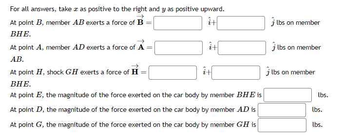
For all answers, take a as positive to the right and y as positive upward. it At point B, member AB exerts a force of B = BHE. i+ At point A, member AD exerts a force of A AB. At point H, shock GH exerts a force of H BHE. At point E, the magnitude of the force exerted on the car body by member BHE is At point D, the magnitude of the force exerted on the car body by member AD is At point G, the magnitude of the force exerted on the car body by member GH is it j lbs on member lbs on member lbs on member lbs. lbs. lbs.


Plane Trusses
It is defined as, two or more elements like beams or any two or more force members, which when assembled together, behaves like a complete structure or as a single structure. They generally consist of two force member which means any component structure where the force is applied only at two points. The point of contact of joints of truss are known as nodes. They are generally made up of triangular patterns. Nodes are the points where all the external forces and the reactionary forces due to them act and shows whether the force is tensile or compressive. There are various characteristics of trusses and are characterized as Simple truss, planar truss or the Space Frame truss.
Equilibrium Equations
If a body is said to be at rest or moving with a uniform velocity, the body is in equilibrium condition. This means that all the forces are balanced in the body. It can be understood with the help of Newton's first law of motion which states that the resultant force on a system is null, where the system remains to be at rest or moves at uniform motion. It is when the rate of the forward reaction is equal to the rate of the backward reaction.
Force Systems
When a body comes in interaction with other bodies, they exert various forces on each other. Any system is under the influence of some kind of force. For example, laptop kept on table exerts force on the table and table exerts equal force on it, hence the system is in balance or equilibrium. When two or more materials interact then more than one force act at a time, hence it is called as force systems.

Step by step
Solved in 3 steps with 3 images


