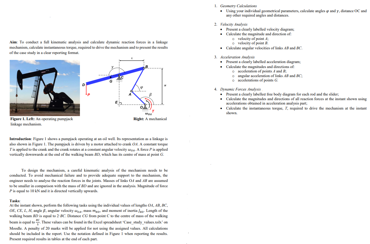
Aim: To conduct a full kinematic analysis and calculate dynamic reaction forces in a linkage mechanism, calculate instantaneous torque, required to drive the mechanism and to present the results of the case study in a clear reporting format. Figure 1. Left: An operating pumpjack linkage mechanism. D G C 9 T WOA Right: A mechanical Introduction: Figure 1 shows a pumpjack operating at an oil well. Its representation as a linkage is also shown in Figure 1. The pumpjack is driven by a motor attached to crank OA. A constant torque T'is applied to the crank and the crank rotates at a constant angular velocity @o. A force P is applied vertically downwards at the end of the walking beam BD, which has its centre of mass at point G. To design the mechanism, a careful kinematic analysis of the mechanism needs to be conducted. To avoid mechanical failure and to provide adequate support to the mechanism, the engineer needs to analyse the reaction forces in the joints. Masses of links OA and AB are assumed to be smaller in comparison with the mass of BD and are ignored in the analysis. Magnitude of force P is equal to 10 kN and it is directed vertically upwards. Tasks: At the instant shown, perform the following tasks using the individual values of lengths OA, AB, BC, OE, CE, L, H, angle ß, angular velocity wOA, mass map, and moment of inertia JBD. Length of the walking beam BD is equal to 2-BC. Distance CG from point C to the centre of mass of the walking beam is equal to These values can be found in the Excel spreadsheet 'Case_study_values.xslx' on BC Moodle. A penalty of 20 marks will be applied for not using the assigned values. All calculations should be included in the report. Use the notation defined in Figure 1 when reporting the results. Present required results in tables at the end of each part. 1. Geometry Calculations Using your individual geometrical parameters, calculate angles op and y, distance OC and any other required angles and distances. 2. Velocity Analysis • Present a clearly labelled velocity diagram; • Calculate the magnitude and direction of: o velocity of point A; o velocity of point B. Calculate angular velocities of links AB and BC. 3. Acceleration Analysis • Present a clearly labelled acceleration diagram; • Calculate the magnitudes and directions of: o acceleration of points A and B; o angular acceleration of links AB and BC; o accelerations of points G. 4. Dynamic Forces Analysis . Present a clearly labelled free body diagram for each rod and the slider; Calculate the magnitudes and directions of all reaction forces at the instant shown using accelerations obtained in acceleration analysis part; Calculate the instantaneous torque, T, required to drive the mechanism at the instant shown.
Aim: To conduct a full kinematic analysis and calculate dynamic reaction forces in a linkage mechanism, calculate instantaneous torque, required to drive the mechanism and to present the results of the case study in a clear reporting format. Figure 1. Left: An operating pumpjack linkage mechanism. D G C 9 T WOA Right: A mechanical Introduction: Figure 1 shows a pumpjack operating at an oil well. Its representation as a linkage is also shown in Figure 1. The pumpjack is driven by a motor attached to crank OA. A constant torque T'is applied to the crank and the crank rotates at a constant angular velocity @o. A force P is applied vertically downwards at the end of the walking beam BD, which has its centre of mass at point G. To design the mechanism, a careful kinematic analysis of the mechanism needs to be conducted. To avoid mechanical failure and to provide adequate support to the mechanism, the engineer needs to analyse the reaction forces in the joints. Masses of links OA and AB are assumed to be smaller in comparison with the mass of BD and are ignored in the analysis. Magnitude of force P is equal to 10 kN and it is directed vertically upwards. Tasks: At the instant shown, perform the following tasks using the individual values of lengths OA, AB, BC, OE, CE, L, H, angle ß, angular velocity wOA, mass map, and moment of inertia JBD. Length of the walking beam BD is equal to 2-BC. Distance CG from point C to the centre of mass of the walking beam is equal to These values can be found in the Excel spreadsheet 'Case_study_values.xslx' on BC Moodle. A penalty of 20 marks will be applied for not using the assigned values. All calculations should be included in the report. Use the notation defined in Figure 1 when reporting the results. Present required results in tables at the end of each part. 1. Geometry Calculations Using your individual geometrical parameters, calculate angles op and y, distance OC and any other required angles and distances. 2. Velocity Analysis • Present a clearly labelled velocity diagram; • Calculate the magnitude and direction of: o velocity of point A; o velocity of point B. Calculate angular velocities of links AB and BC. 3. Acceleration Analysis • Present a clearly labelled acceleration diagram; • Calculate the magnitudes and directions of: o acceleration of points A and B; o angular acceleration of links AB and BC; o accelerations of points G. 4. Dynamic Forces Analysis . Present a clearly labelled free body diagram for each rod and the slider; Calculate the magnitudes and directions of all reaction forces at the instant shown using accelerations obtained in acceleration analysis part; Calculate the instantaneous torque, T, required to drive the mechanism at the instant shown.

Elements Of Electromagnetics
7th Edition
ISBN:9780190698614
Author:Sadiku, Matthew N. O.
Publisher:Sadiku, Matthew N. O.
ChapterMA: Math Assessment
Section: Chapter Questions
Problem 1.1MA

Related questions

Question
I have found the following values so far and have been able to understand and complete question one.
OA = 0.75m, AB = 4.00m, BC = 3.50m, BD = 7.00m, CG = 0.70m, OE = 2.40m, CE = 2.25m, L = 2.63m, H = 4.56m
beta = 125 degrees, omegaOA = 3.8 rad/s, mOD = 2400kg, JBD = 2800kg m2
phi = 80.54 degrees, gamma = 138.70 degrees, OC = 3.29m
Transcribed Image Text:Aim: To conduct a full kinematic analysis and calculate dynamic reaction forces in a linkage
mechanism, calculate instantaneous torque, required to drive the mechanism and to present the results
of the case study in a clear reporting format.
Figure 1. Left: An operating pumpjack
linkage mechanism.
D
----
G
C
20
4
B
T
WOA
Right: A mechanical
Introduction: Figure 1 shows a pumpjack operating at an oil well. Its representation as a linkage is
also shown in Figure 1. The pumpjack is driven by a motor attached to crank OA. A constant torque
T' is applied to the crank and the crank rotates at a constant angular velocity WoA. A force P is applied
vertically downwards at the end of the walking beam BD, which has its centre of mass at point G.
To design the mechanism, a careful kinematic analysis of the mechanism needs to be
conducted. To avoid mechanical failure and to provide adequate support to the mechanism, the
engineer needs to analyse the reaction forces in the joints. Masses of links OA and AB are assumed
to be smaller in comparison with the mass of BD and are ignored in the analysis. Magnitude of force
P is equal to 10 kN and it is directed vertically upwards.
Tasks:
At the instant shown, perform the following tasks using the individual values of lengths OA, AB, BC,
OE, CE, L, H, angle B, angular velocity @o, mass mgp, and moment of inertia JBD. Length of the
walking beam BD is equal to 2-BC. Distance CG from point C to the centre of mass of the walking
beam is equal to. These values can be found in the Excel spreadsheet 'Case_study_values.xslx' on
Moodle. A penalty of 20 marks will be applied for not using the assigned values. All calculations
should be included in the report. Use the notation defined in Figure 1 when reporting the results.
Present required results in tables at the end of each part.
1. Geometry Calculations
• Using your individual geometrical parameters, calculate angles and y, distance OC and
any other required angles and distances.
2. Velocity Analysis
• Present a clearly labelled velocity diagram;
Calculate the magnitude and direction of:
o velocity of point A;
o velocity of point B.
• Calculate angular velocities of links AB and BC.
3. Acceleration Analysis
• Present a clearly labelled acceleration diagram;
Calculate the magnitudes and directions of:
o acceleration of points A and B;
o angular acceleration of links AB and BC;
o accelerations of points G.
4. Dynamic Forces Analysis
Present a clearly labelled free body diagram for each rod and the slider;
Calculate the magnitudes and directions of all reaction forces at the instant shown using
accelerations obtained in acceleration analysis part;
Calculate the instantaneous torque, T, required to drive the mechanism at the instant
shown.
Expert Solution
This question has been solved!
Explore an expertly crafted, step-by-step solution for a thorough understanding of key concepts.

This is a popular solution!

Trending now
This is a popular solution!

Step by step
Solved in 5 steps with 8 images

Follow-up Questions
Read through expert solutions to related follow-up questions below.
Follow-up Question
For the acceleration analysis question, how do you find tangential acceleration ab (a^t ab)?
Solution
Knowledge Booster


Learn more about
Need a deep-dive on the concept behind this application? Look no further. Learn more about this topic, mechanical-engineering and related others by exploring similar questions and additional content below.Recommended textbooks for you
Elements Of Electromagnetics
Mechanical Engineering
ISBN:
9780190698614
Author:
Sadiku, Matthew N. O.
Publisher:
Oxford University Press

Mechanics of Materials (10th Edition)
Mechanical Engineering
ISBN:
9780134319650
Author:
Russell C. Hibbeler
Publisher:
PEARSON

Thermodynamics: An Engineering Approach
Mechanical Engineering
ISBN:
9781259822674
Author:
Yunus A. Cengel Dr., Michael A. Boles
Publisher:
McGraw-Hill Education
Elements Of Electromagnetics
Mechanical Engineering
ISBN:
9780190698614
Author:
Sadiku, Matthew N. O.
Publisher:
Oxford University Press
Mechanics of Materials (10th Edition)
Mechanical Engineering
ISBN:
9780134319650
Author:
Russell C. Hibbeler
Publisher:
PEARSON
Thermodynamics: An Engineering Approach
Mechanical Engineering
ISBN:
9781259822674
Author:
Yunus A. Cengel Dr., Michael A. Boles
Publisher:
McGraw-Hill Education

Control Systems Engineering
Mechanical Engineering
ISBN:
9781118170519
Author:
Norman S. Nise
Publisher:
WILEY

Mechanics of Materials (MindTap Course List)
Mechanical Engineering
ISBN:
9781337093347
Author:
Barry J. Goodno, James M. Gere
Publisher:
Cengage Learning

Engineering Mechanics: Statics
Mechanical Engineering
ISBN:
9781118807330
Author:
James L. Meriam, L. G. Kraige, J. N. Bolton
Publisher:
WILEY