For the cantilever truss shown in Figure 1-103, Determine the force in members DF. FH. FI, GI, and FG. H B 24' 16' A E G 500 lb 1000 lb 1000 lb Figure 1-103 20' 16' C 500 lb 20' 20' 20' 40'
For the cantilever truss shown in Figure 1-103, Determine the force in members DF. FH. FI, GI, and FG. H B 24' 16' A E G 500 lb 1000 lb 1000 lb Figure 1-103 20' 16' C 500 lb 20' 20' 20' 40'

Mechanics of Materials (MindTap Course List)
9th Edition
ISBN:9781337093347
Author:Barry J. Goodno, James M. Gere
Publisher:Barry J. Goodno, James M. Gere
Chapter1: Tension, Compression, And Shear
Section: Chapter Questions
Problem 1.9.9P: A lifeboat hangs from two ship's davits. as shown in the figure. A pin of diameter d = 0.80 in....

Related questions

Question
Draw the free body diagram
Always use 3 decimal places
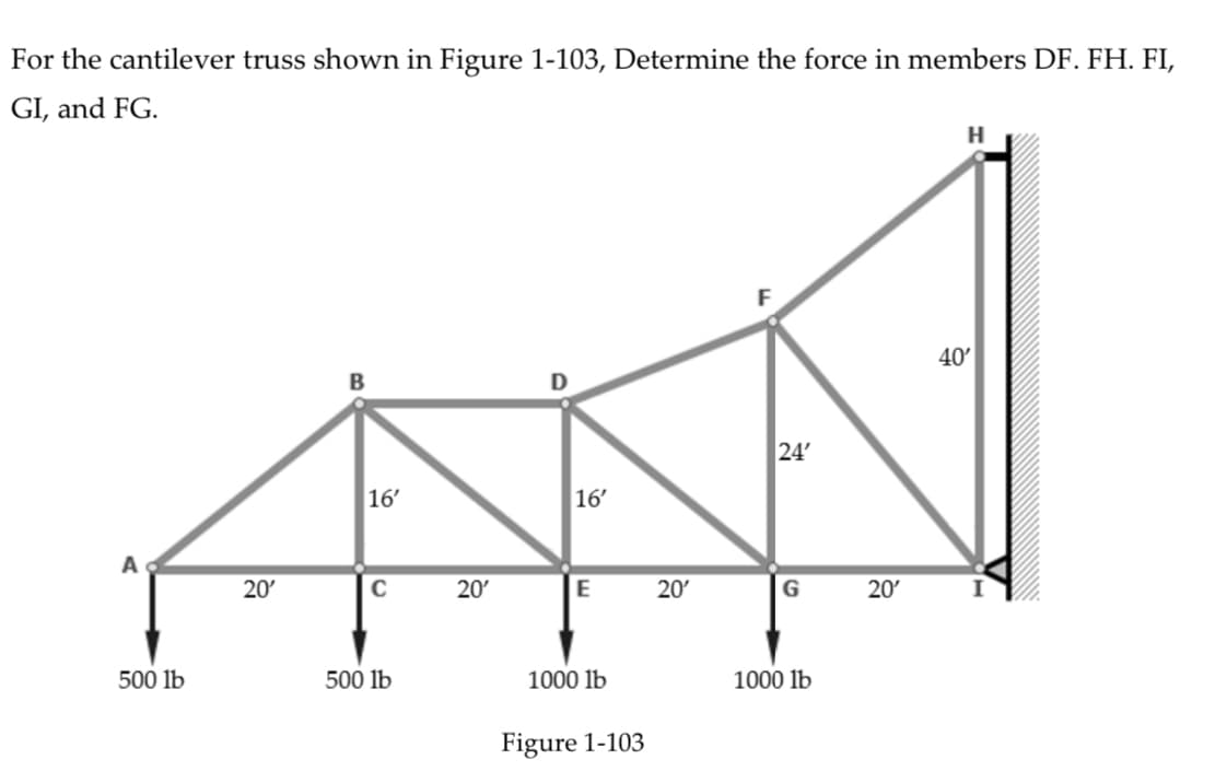
Transcribed Image Text:For the cantilever truss shown in Figure 1-103, Determine the force in members DF. FH. FI,
GI, and FG.
H
B
24'
16'
A
E
G
500 lb
1000 lb
1000 lb
Figure 1-103
20'
16'
C
500 lb
20'
20'
20'
40'
Expert Solution
This question has been solved!
Explore an expertly crafted, step-by-step solution for a thorough understanding of key concepts.

Step by step
Solved in 4 steps with 4 images

Knowledge Booster


Learn more about
Need a deep-dive on the concept behind this application? Look no further. Learn more about this topic, mechanical-engineering and related others by exploring similar questions and additional content below.Recommended textbooks for you
Mechanics of Materials (MindTap Course List)
Mechanical Engineering
ISBN:
9781337093347
Author:
Barry J. Goodno, James M. Gere
Publisher:
Cengage Learning
Mechanics of Materials (MindTap Course List)
Mechanical Engineering
ISBN:
9781337093347
Author:
Barry J. Goodno, James M. Gere
Publisher:
Cengage Learning