For the circuit in Figure 1, Clock and D input signal waveforms are as shown in Figure 5. Which one of the following diagrams show the correct timing diagrams for the signals S1, S2 and Q corresponding to the given inputs? Note: As the propagation delays are so small, they are not shown on the diagrams. Initial value for Q is '1: Clock. D Figure 5 Clock D si S2 Clock s1 S2 Clock D S2 Q
For the circuit in Figure 1, Clock and D input signal waveforms are as shown in Figure 5. Which one of the following diagrams show the correct timing diagrams for the signals S1, S2 and Q corresponding to the given inputs? Note: As the propagation delays are so small, they are not shown on the diagrams. Initial value for Q is '1: Clock. D Figure 5 Clock D si S2 Clock s1 S2 Clock D S2 Q

Electricity for Refrigeration, Heating, and Air Conditioning (MindTap Course List)
10th Edition
ISBN:9781337399128
Author:Russell E. Smith
Publisher:Russell E. Smith
Chapter11: Thermostats, Pressure Switches, And Other Electric Control Devices
Section: Chapter Questions
Problem 32RQ

Related questions

Question
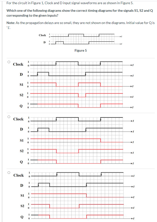
Transcribed Image Text:For the circuit in Figure 1, Clock and D input signal waveforms are as shown in Figure 5.
Which one of the following diagrams show the correct timing diagrams for the signals S1, S2 and Q
corresponding to the given inputs?
Note: As the propagation delays are so small, they are not shown on the diagrams. Initial value for Qis
1.
Clock:
Figure 5
Clock
D
1
si
S2
Clock
D
1
1
S2
Clock
D
si
S2
Q
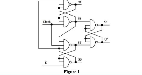
Transcribed Image Text:Clock
SI
S2
Figure 1
Expert Solution
This question has been solved!
Explore an expertly crafted, step-by-step solution for a thorough understanding of key concepts.

Step by step
Solved in 2 steps

Knowledge Booster


Learn more about
Need a deep-dive on the concept behind this application? Look no further. Learn more about this topic, electrical-engineering and related others by exploring similar questions and additional content below.Recommended textbooks for you
Electricity for Refrigeration, Heating, and Air C…
Mechanical Engineering
ISBN:
9781337399128
Author:
Russell E. Smith
Publisher:
Cengage Learning
Electricity for Refrigeration, Heating, and Air C…
Mechanical Engineering
ISBN:
9781337399128
Author:
Russell E. Smith
Publisher:
Cengage Learning