For the circuit involving ideal op amps shown in the image below, if R1 = 11 k2, R2 = 11 kS2, R3 = 14 k2, and R4 = 25 k2, determine the output voltage vo. %3D Please pay attention: the numbers may change since they are randomized. Your answer must include 2 places after the decimal point, and the proper Sl unit. 60 k2 R, 5V(* R3 R4 R2 + 5V Your Answer: Answer units
For the circuit involving ideal op amps shown in the image below, if R1 = 11 k2, R2 = 11 kS2, R3 = 14 k2, and R4 = 25 k2, determine the output voltage vo. %3D Please pay attention: the numbers may change since they are randomized. Your answer must include 2 places after the decimal point, and the proper Sl unit. 60 k2 R, 5V(* R3 R4 R2 + 5V Your Answer: Answer units

Delmar's Standard Textbook Of Electricity
7th Edition
ISBN:9781337900348
Author:Stephen L. Herman
Publisher:Stephen L. Herman
Chapter18: Resistive-inductive Parallel Circuits
Section: Chapter Questions
Problem 13PP: In an R-L parallel circuit, IT=1.25 amps, R=1.2k, and XL=1k. Find IR

Related questions

Question
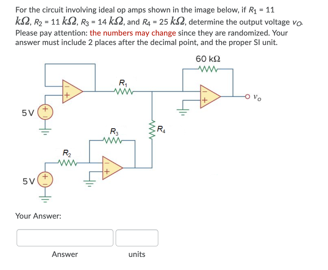
Transcribed Image Text:For the circuit involving ideal op amps shown in the image below, if R1
= 11
k2, R2 = 11 k2, R3 = 14 k2, and R4 = 25 kS2, determine the output voltage vo.
Please pay attention: the numbers may change since they are randomized. Your
answer must include 2 places after the decimal point, and the proper Sl unit.
60 k2
R,
Vo
5V
R3
R4
R2
5V
Your Answer:
Answer
units
Expert Solution
This question has been solved!
Explore an expertly crafted, step-by-step solution for a thorough understanding of key concepts.

This is a popular solution!

Trending now
This is a popular solution!

Step by step
Solved in 2 steps with 3 images

Knowledge Booster


Learn more about
Need a deep-dive on the concept behind this application? Look no further. Learn more about this topic, electrical-engineering and related others by exploring similar questions and additional content below.Recommended textbooks for you
Delmar's Standard Textbook Of Electricity
Electrical Engineering
ISBN:
9781337900348
Author:
Stephen L. Herman
Publisher:
Cengage Learning
Delmar's Standard Textbook Of Electricity
Electrical Engineering
ISBN:
9781337900348
Author:
Stephen L. Herman
Publisher:
Cengage Learning